Avensis (2012) - Car TOYOTA - Free user manual and instructions
Find the device manual for free Avensis (2012) TOYOTA in PDF.

User questions about Avensis (2012) TOYOTA
0 question about this device. Answer the ones you know or ask your own.
Ask a new question about this device
Download the instructions for your Car in PDF format for free! Find your manual Avensis (2012) - TOYOTA and take your electronic device back in hand. On this page are published all the documents necessary for the use of your device. Avensis (2012) by TOYOTA.
USER MANUAL Avensis (2012) TOYOTA
| 1 | Before driving | Adjusting and operating features such as door locks, mirrors, and steering column | |
| 2 | When driving | Driving, stopping and safe-driving information | |
| 3 | Interior features | Air conditioning and audio systems, as well as other interior features for a comfortable driving experience | |
| 4 | Maintenance and care | Cleaning and protecting your vehicle, performing do-it-yourself maintenance, and maintenance information | |
| 5 | When trouble arises | What to do if the vehicle needs to be towed, gets a flat tire, or is involved in an accident | |
| 6 | Vehicle specifications | Detailed vehicle information | |
| Index | Alphabetical listing of information contained in this manual |
TABLE OF CONTENTS Index
For vehicles with a "touch screen", refer to the "touch screen" Owner's Manual" for information regarding the equipment listed below.
- Navigation system
- Audio/video system
- Rear view monitor system
1 Before driving
1-1. Key information
Keys...... 36
1-2. Opening, closing and locking the doors
Smart entry & start system 39
Wireless remote control ..... 62
Side doors....78
Trunk (sedan) 88
Back door (wagon).... 92
1-3. Adjustable components (seats, mirrors, steering wheel)
Front seats.... 98
Rear seats 100
Driving position memory system 103
Head restraints .... 106
Seat belts.... 108
Steering wheel 116
Inside rear view mirror ..... 119
Outside rear view mirrors .... 122
1-4. Opening and closing the windows
Power windows 125
1-5. Refueling
Opening the fuel tank cap 129
1-6. Theft deterrent system
Engine immobilizer system.... 135
Double locking system ..... 144
Alarm.... 146
1-7. Safety information
Correct driving posture..... 154
SRS airbags 156
Child restraint systems..... 168
Installing child restraints..... 176
Airbag manual on-off system.... 190
2 When driving
2-1. Driving procedures
Driving the vehicle 194
Engine (ignition) switch (vehicles with smart entry & start system)...... 210
Engine (ignition) switch (vehicles without smart entry & start system)...... 215
Multidrive 219
Automatic transmission..... 225
Manual transmission...... 232
Turn signal lever 236
Parking brake.... 237
Horn 241
2-2. Instrument cluster
Gauges and meters ..... 242
Indicators and warning lights 245
Multi-information display ..... 249
2-3. Operating the lights and wipers
Headlight switch 262
Fog light switch 267
Windshield wipers and washer 269
Rear window wiper and washer (wagon) ...... 274
2-4. Using other driving systems
Cruise control 275
Dynamic radar cruise control 281
Speed limiter 300
Toyota parking assist-sensor.... 303
Rear view monitor system.... 308
LKA (Lane-Keeping Assist) 318
Driving assist systems...... 327
PCS (Pre-Crash Safety)..... 333
2-5. Driving information
Cargo and luggage...... 342
Winter driving tips.... 344
Trailer towing.... 348
1
2
3
4
5
6
3 Interior features
3-1. Using the air conditioning system and defogger
Automatic air conditioning system 360
Manual air conditioning system 370
Power heater 378
Rear window and outside rear view mirror defoggers.... 381
Windshield wiper de-icer.... 382
3-2. Using the audio system
Audio system types ...... 383
Using the radio 391
Using the CD player ..... 398
Playing back MP3 and WMA discs 406
Operating an iPod 416
Operating a USB memory 426
Optimal use of the audio system.... 436
Using the AUX port ...... 438
Using the steering wheel audio switches 439
Bluetooth ^® audio/phone ..... 442
Using the Bluetooth ^® audio/phone 449
Operating a Bluetooth ^® enabled portable player 455
Making a phone call 459
Using the "SET UP" menu ("Bluetooth" menu) 465
Using the "SET UP" menu ("TEL" menu).... 471
3-3. Using the interior lights
Interior lights list 478
- Personal/interior light main switch 479
• Personal/interior lights ..... 479
• Personal lights 480
3-4. Using the storage features
List of storage features ..... 481
• Glove box 482
- Console box...... 483
• Overhead console ..... 484
• Cup holders 485
- Bottle holders...... 486
- Coin box 488
3-5. Other interior features
Sunvisors 489
Vanity mirror 490
Ashtray.... 491
Cigarette lighter 492
Power outlet...... 493
Seat heaters 494
Armrest 496
Trunk/luggage
compartment storage
extension .... 497
Panoramic roof shade (wagon).... 498
Rear sunshade (sedan) ..... 501
Rear side sunshades
(sedan) 502
Floor mats.... 503
Trunk features (sedan) ..... 505
Luggage compartment
features (wagon)...... 507
4 Maintenance and care
4-1. Maintenance and care
Cleaning and protecting the vehicle exterior...... 516
Cleaning and protecting the vehicle interior.... 521
4-2. Maintenance
Maintenance requirements 524
4-3. Do-it-yourself maintenance
Do-it-yourself service precautions 527
Hood.... 531
Positioning a floor jack ..... 533
Engine compartment ..... 535
Tires 552
Tire inflation pressure...... 556
Wheels 558
Air conditioning filter...... 560
Key battery 564
Checking and replacing fuses 569
Light bulbs.... 585
1
2
3
4
5
6
5 When trouble arises
5-1. Essential information
Emergency flashers ...... 604
If your vehicle needs to be towed 605
If you think something is wrong 615
Fuel pump shut off system (gasoline engine) 616
5-2. Steps to take in an emergency
If a warning light turns on or a warning buzzer sounds... 617
If a warning message is displayed.... 624
If you have a flat tire (vehicles with a spare tire for sedan) 648
If you have a flat tire (vehicles with a spare tire for wagon).... 662
If you have a flat tire (vehicles without a spare tire) 676
If the engine will not start.... 689
If the shift lever cannot be shifted from "P" 692
If the parking brake cannot be released ...... 693
If you lose your keys ...... 699
If you cannot operate the trunk opener (sedan).... 700
If you cannot operate the back door opener (wagon) 701
If the electronic key does not operate properly.... 702
If the battery is discharged 705
If your vehicle overheats .... 710
If you run out of fuel and the engine stalls (diesel engine) 713
If the vehicle becomes stuck.... 714
If your vehicle has to be stopped in an emergency 716
6 Vehicle specifications
6-1. Specifications
Maintenance data (fuel, oil level, etc.).... 720 Fuel information .... 745
6-2. Customization
Customizable features ..... 749
6-3. Initialization
Items to initialize 754
Index
Abbreviation list...... 756
Alphabetical index ...... 757
What to do if.... 766
Pictorial index
Exterior (sedan)

text_image
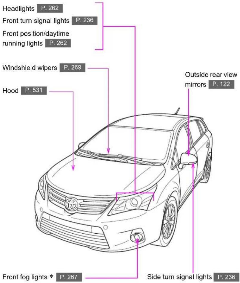
Headlights P. 262 Front turn signal lights P. 236 Front position/daytime running lights P. 262 Windshield wipers P. 269 Hood P. 531 Outside rear view mirrors P. 122 Front fog lights * P. 267 Side turn signal lights P. 236
text_image
Rear window defogger P. 381 Tail lights P. 262 Fuel filler door P. 129 Side doors P. 78 Tires • Rotation P. 552 • Replacement P. 648, 676 • Inflation pressure P. 556 Trunk P. 88 Rear fog light (right-hand drive vehicles) P. 267 License plate lights P. 262 Rear view monitor system camera ** P. 313 Rear fog light (left-hand drive vehicles) P. 267 Rear turn signal lights P. 236*: If equipped
*: For vehicles with a "touch screen", refer to "touch screen" Owner's Manual".
Pictorial index
Exterior (wagon)
text_image
Headlights P. 262 Front turn signal lights P. 236 Front position/daytime running lights P. 262 Windshield wipers P. 269 Hood P. 531 Outside rear view mirrors P. 122 Front fog lights * P. 267 Side turn signal lights P. 236
text_image
Rear window defogger P. 381 Tail lights P. 262 Fuel filler door P. 129 Side doors P. 78 Tires • Rotation P. 552 • Replacement P. 662, 676 • Inflation pressure P. 556 Rear turn signal lights P. 236 Rear window wiper P. 274 Rear fog light (right-hand drive vehicles) P. 267 License plate lights P. 262 Rear view monitor system camera * P. 313 Back door P. 92 Rear fog light (left-hand drive vehicles) P. 267*: If equipped
*: For vehicles with a "touch screen", refer to "touch screen" Owner's Manual".
Pictorial index
Interior
(left-hand drive vehicles)
text_image
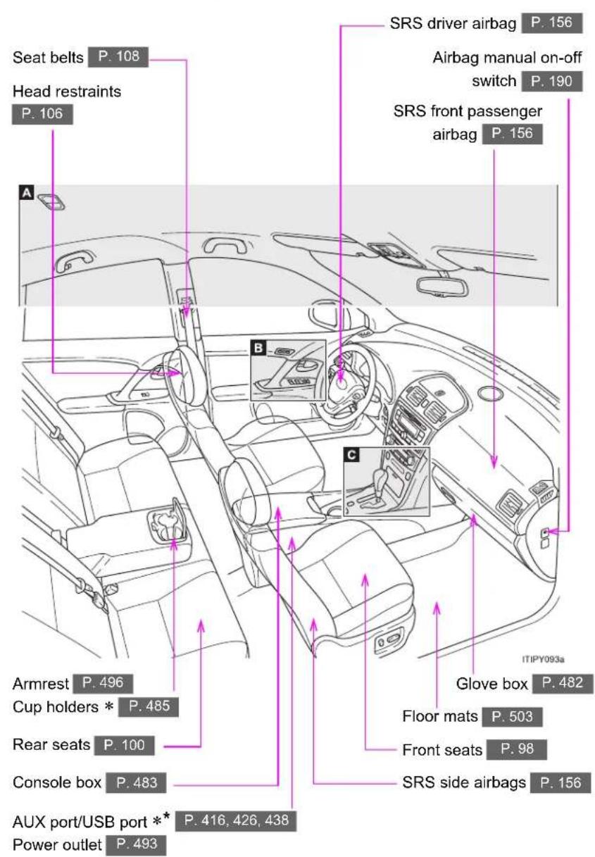
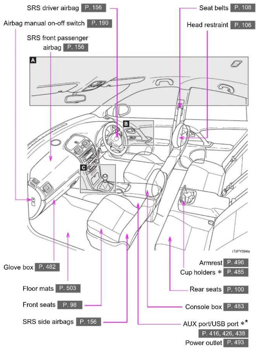
Seat belts P. 108 Head restraints P. 106 A SRS driver airbag P. 156 Airbag manual on-off switch P. 190 SRS front passenger airbag P. 156 Armrest P. 496 Cup holders * P. 485 Rear seats P. 100 Console box P. 483 AUX port/USB port ** P. 416, 426, 438 Power outlet P. 493 ITIPY093a Glove box P. 482 Floor mats P. 503 Front seats P. 98 SRS side airbags P. 156A

text_image
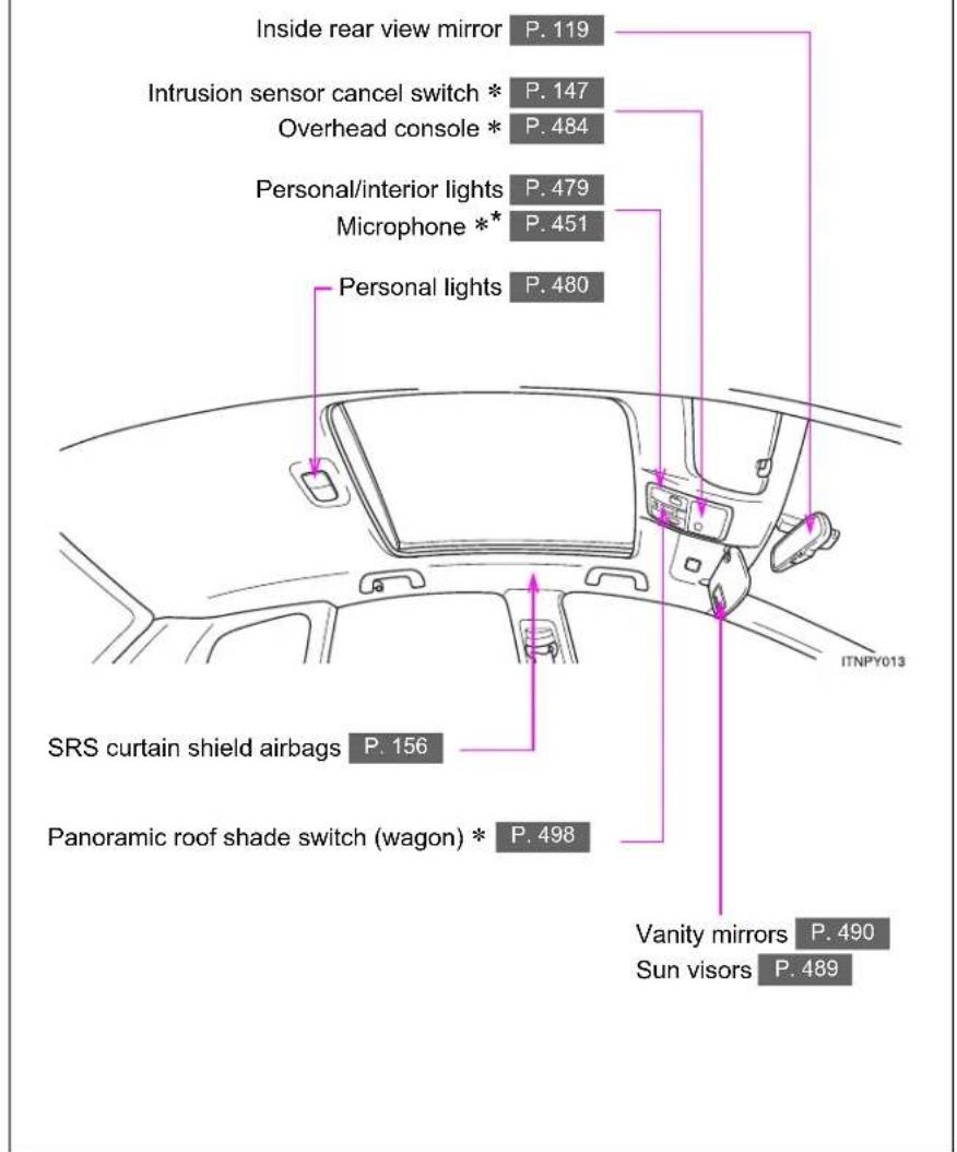
Inside rear view mirror P. 119 Intrusion sensor cancel switch * P. 147 Overhead console * P. 484 Personal/interior lights P. 479 Microphone ** P. 451 Personal lights P. 480 SRS curtain shield airbags P. 156 Panoramic roof shade switch (wagon) * P. 498 Vanity mirrors P. 490 Sun visors P. 489*: If equipped
*: For vehicles with a "touch screen", refer to "touch screen" Owner's Manual".
Pictorial index
Interior
(left-hand drive vehicles)
B
text_image
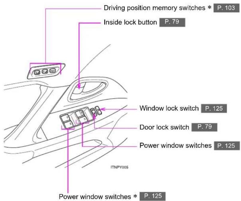
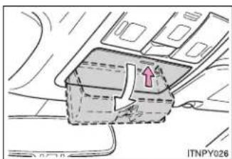
Driving position memory switches * P. 103 Inside lock button P. 79 Window lock switch P. 125 Door lock switch P. 79 Power window switches P. 125 ITNPY005 Power window switches * P. 125C
text_image
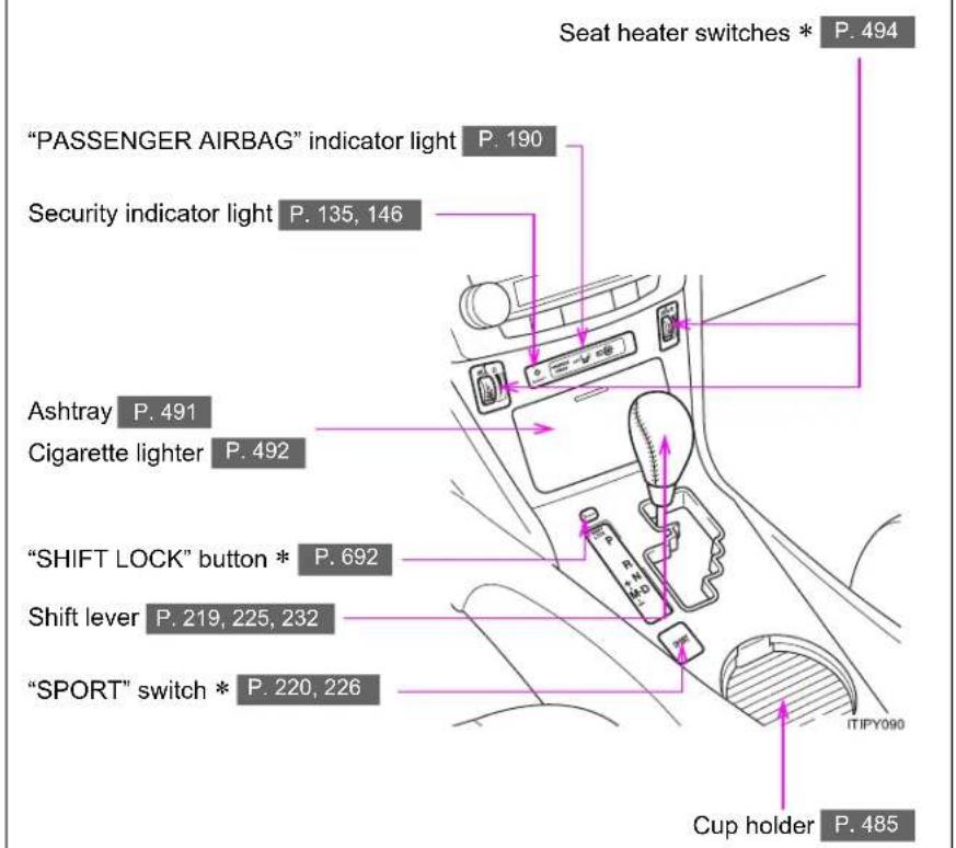
Seat heater switches * P. 494 "PASSENGER AIRBAG" indicator light P. 190 Security indicator light P. 135, 146 Ashtray P. 491 Cigarette lighter P. 492 "SHIFT LOCK" button * P. 692 Shift lever P. 219, 225, 232 "SPORT" switch * P. 220, 226 Cup holder P. 485*: If equipped
Pictorial index
Instrument panel (left-hand drive vehicles)
Gauges and meters P. 242
Multi-information display P. 249
Headlight switch P. 262
Turn signal lever P. 236
Fog light switch P. 267
text_image
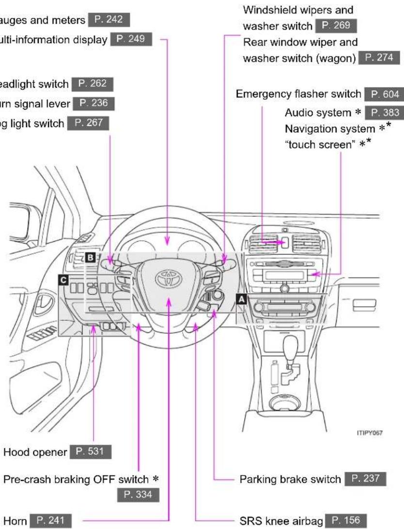
auges and meters P. 242 multi-information display P. 249 headlight switch P. 262 orn signal lever P. 236 ing light switch P. 267 B C A Hood opener P. 531 Pre-crash braking OFF switch * P. 334 Horn P. 241 Windshield wipers and washer switch P. 269 Rear window wiper and washer switch (wagon) P. 274 Emergency flasher switch P. 604 Audio system * P. 383 Navigation system ** "touch screen" ** ITIPY057 Parking brake switch P. 237 SRS knee airbag P. 156A
▶ Vehicles with automatic air conditioning system

text_image
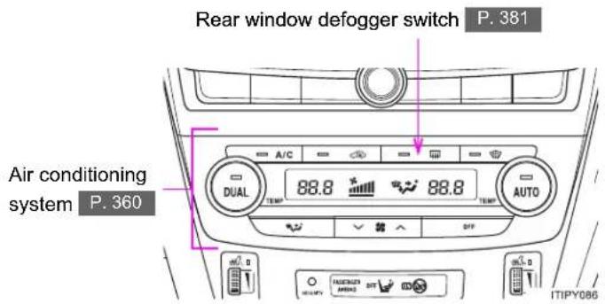
Rear window defogger switch P. 381 Air conditioning system P. 360 98.8 ° AUTO A/C 98.8 DUAL ITIPY082 Windshield wiper de-icer switch * P. 382 Power heater switch * P. 378▶ Vehicles with manual air conditioning system

text_image
Rear window defogger switch P. 381 Air conditioning system P. 370 Windshield wiper de-icer switch * P. 382 Power heater switch * P. 378*: If equipped
*: Refer to "touch screen" Owner's Manual".
Pictorial index
Instrument panel (left-hand drive vehicles)
B

text_image
Telephone switches * P. 451 "DISP" switch * P. 250 Distance switch * P. 281 "DISP" switch * P. 250 Paddle shift switches * P. 221, 227 Talk switch * P. 451 Audio remote control switches P. 439 Cruise control switch * P. 275, 281 Engine (ignition) switch (vehicles without smart entry & start system) P. 215 Engine (ignition) switch (vehicles with smart entry & start system) P. 210C

text_image
"LKA" switch * P. 318 Headlight leveling dial * P. 264 Outside rear view mirror switches P. 122 Speed limiter switch * P. 300 Toyota parking assist-sensor switch * P. 303 Tilt and telescopic steering control switch * P. 116 Tilt and telescopic steering lock release lever * P. 116 Coin box P. 488 "AFS OFF" switch * P. 263 VSC OFF switch P. 328 Fuel filler door opener P. 129*: If equipped
*: For vehicles with a "touch screen", refer to "touch screen" Owner's Manual".
Pictorial index
Interior
(right-hand drive vehicles)
text_image
SRS driver airbag P. 156 Airbag manual on-off switch P. 190 SRS front passenger airbag P. 156 A Seat belts P. 108 Head restraint P. 106 B C Glove box P. 482 Floor mats P. 503 Front seats P. 98 SRS side airbags P. 156 Armrest P. 496 Cup holders * P. 485 Rear seats P. 100 Console box P. 483 AUX port/USB port ** P. 416, 426, 438 Power outlet P. 493 ITIPY094aA
text_image
Inside rear view mirror P. 119 Intrusion sensor cancel switch * P. 147 Overhead console * P. 484 Personal/interior lights P. 479 Microphone ** P. 451 Personal lights P. 480 SRS curtain shield airbags P. 156 Panoramic roof shade switch (wagon) * P. 498 Vanity mirrors P. 490 Sun visors P. 489 ITNPY013*: If equipped
*: For vehicles with a "touch screen", refer to "touch screen" Owner's Manual".
Pictorial index
Interior
(right-hand drive vehicles)
B

text_image
Window lock switch P. 125 Inside lock button P. 79 Driving position memory switches * P. 103 Power window switches * P. 125 ITNPY014 Power window switches P. 125 Door lock switch P. 79C

text_image
"PASSENGER AIRBAG" indicator light P. 190 Security indicator light P. 135, 146 Seat heater switches * P. 494 Shift lever P. 219, 225, 232 "SHIFT LOCK" button * P. 692 Cup holder P. 485 "SPORT" switch * P. 220, 226 Ashtray P. 491 Cigarette lighter P. 492*: If equipped
Pictorial index
Instrument panel (right-hand drive vehicles)

text_image
Headlight switch P. 262 Turn signal lever P. 236 Fog light switch P. 267 Emergency flasher switch P. 604 Audio system ** P. 383 Navigation system ** "touch screen" ** Gauges and meters P. 242 Multi-information display P. 249 Windshield wipers and washer switch P. 269 Rear window wiper and washer switch (wagon) P. 274 A B C Pricing brake switch P. 237 SRS knee airbag P. 156 Hood opener P. 531 Pre-crash braking OFF switch * P. 334 Horn P. 241A
▶ Vehicle with automatic air conditioning system
text_image
Rear window defogger switch P. 381 Air conditioning system P. 360 A/C DUAL 88.8 °C 88.8 TEMP TEMP AUTO ITIPY086▶ Vehicle with manual air conditioning system
text_image
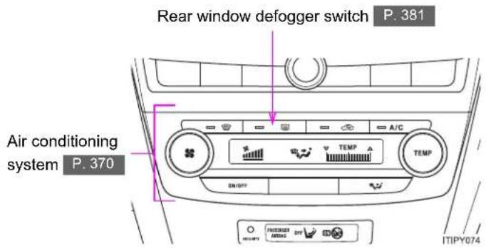
Rear window defogger switch P. 381 Air conditioning system P. 370 A/C TEMP TEMP SW/SP INTIPY074*: If equipped
*: Refer to "touch screen" Owner's Manual".
Pictorial index
Instrument panel (right-hand drive vehicles)
B

text_image
Audio remote control switches P. 439 Telephone switches * P. 451 "DISP" switch * P. 250 Paddle shift switches * P. 221, 227 Talk switch * P. 451 "DISP" switch * P. 250 ITNPY016 Toyota parking assist-sensor switch * P. 303 Distance switch * P. 281 Cruise control switch * P. 275, 281 Tilt and telescopic steering control switch * P. 116 Tilt and telescopic steering lock release lever * P. 116C

text_image
"LKA" switch * P. 318 Headlight leveling dial * P. 264 Outside rear view mirror switches P. 122 Speed limiter switch * P. 300 Engine (ignition) switch (vehicles with smart entry & start system) P. 210 Engine (ignition) switch (vehicles without smart entry & start system) P. 215 Coin box P. 488 "AFS OFF" switch * P. 263 VSC OFF switch P. 328 Fuel filler door opener P. 129*: If equipped
*: For vehicles with a "touch screen", refer to "touch screen" Owner's Manual".
Pictorial index
Luggage compartment (wagon)
▶ With deck rail

text_image
Separation net * P. 510 Luggage cover * P. 509 ISOFIX rigid anchor P. 177 Luggage mat P. 508 Cargo hook P. 507 Deck side board * P. 509 ITIPY088▶ Without deck rail

text_image
Separation net * P. 510 Luggage cover * P. 509 ISOFIX rigid anchor P. 177 ITIPY089 Luggage mat P. 508 Cargo hook P. 507 Deck side board * P. 509*: If equipped
For your information
Main Owner's Manual
Please note that this manual covers all models and all equipment, including options. Therefore, you may find some explanations for equipment not installed on your vehicle.
All specifications provided in this manual are current at the time of printing. However, because of the Toyota policy of continual product improvement, we reserve the right to make changes at any time without notice.
Depending on specifications, the vehicle shown in the illustrations may differ from your vehicle in terms of equipment.
Accessories, spare parts and modification of your Toyota
Both genuine Toyota and a wide variety of other spare parts and accessories for Toyota vehicles are currently available on the market. Should it be determined that any of the genuine Toyota parts or accessories supplied with the vehicle need to be replaced, Toyota Motor Corporation recommends that genuine Toyota parts or accessories, be used to replace them. Other parts or accessories of matching quality can also be used. Toyota cannot accept any liability or guarantee spare parts and accessories which are not genuine Toyota products, nor for replacement or installation involving such parts. In addition, damage or performance problems resulting from the use of non-genuine Toyota spare parts or accessories may not be covered under warranty.
Installation of an RF-transmitter system
The installation of an RF-transmitter system in your vehicle could affect electronic systems such as:
- Multiport fuel injection system/sequential multiport fuel injection system
● Dynamic radar cruise control - Cruise control system
- Anti-lock brake system
- SRS airbag system
- Seat belt pretensioner system
Be sure to check with any authorized Toyota dealer or repairer, or another duly qualified and equipped professional for precautionary measures or special instructions regarding installation.
Further information regarding frequency bands, power levels, antenna positions and installation provisions for the installation of RF-transmitters, is available on request at any authorized Toyota dealer or repairer, or another duly qualified and equipped professional.
Scrapping of your Toyota
The SRS airbag and seat belt pretensioner devices in your Toyota contain explosive chemicals. If the vehicle is scrapped with the airbags and seat belt pretensioners left as they are, this may cause an accident such as fire. Be sure to have the systems of the SRS airbag and seat belt pretensioner removed and disposed of by a qualified service shop or by any authorized Toyota dealer or repairer, or another duly qualified and equipped professional, before you scrap your vehicle.

CAUTION
■ General precautions while driving
Driving under the influence: Never drive your vehicle when under the influence of alcohol or drugs that have impaired your ability to operate your vehicle. Alcohol and certain drugs delay reaction time, impair judgment and reduce coordination, which could lead to an accident that could result in death or serious injury.
Defensive driving: Always drive defensively. Anticipate mistakes that other drivers or pedestrians might make and be ready to avoid accidents.
Driver distraction: Always give your full attention to driving. Anything that distracts the driver, such as adjusting controls, talking on a cellular phone or reading can result in a collision with resulting death or serious injury to you, your occupants or others.
■ General precaution regarding children's safety
Never leave children unattended in the vehicle, and never allow children to have or use the key.
Children may be able to start the vehicle or shift the vehicle into neutral. There is also a danger that children may injure themselves by playing with the cigarette lighter, the windows, or other features of the vehicle. In addition, heat build-up or extremely cold temperatures inside the vehicle can be fatal to children.
Your vehicle contains batteries and/or accumulators. Do not discard them into the environment but cooperate with separate collection (Directive 2006/66/EC).
Symbols used throughout this manual
Cautions & Notices

CAUTION
This is a warning against anything which may cause injury to people if the warning is ignored. You are informed about what you must or must not do in order to reduce the risk of injury to yourself and others.

NOTICE
This is a warning against anything which may cause damage to the vehicle or its equipment if the warning is ignored. You are informed about what you must or must not do in order to avoid or reduce the risk of damage to your Toyota and its equipment.
Symbols used in illustrations

Safety symbol
The symbol of a circle with a slash through it means "Do not", "Do not do this", or "Do not let this happen".
natural_image
Diagram of a vehicle interior with a highlighted section and directional arrow (no text or symbols)Arrows indicating operations

Indicates the action (pushing, turning, etc.) used to operate switches and other devices.

Indicates the outcome of an operation (e.g. a lid opens).
Before driving
1
1-1. Key information
Keys...... 36
1-2. Opening, closing and locking the doors
Smart entry & start system 39
Wireless remote control..... 62
Side doors 78
Trunk (sedan) 88
1-3. Adjustable components (seats, mirrors, steering wheel)
Front seats.... 98
Rear seats 100
Driving position memory system 103
Head restraints 106
Seat belts.... 108
Steering wheel.... 116
Inside rear view mirror ..... 119
Outside rear view mirrors 122
1-4. Opening and closing the windows
Power windows.... 125
1-5. Refueling
Opening the fuel tank cap 129
1-6. Theft deterrent system
Engine immobilizer system 135
Double locking system..... 144
Alarm 146
1-7. Safety information
Correct driving posture ..... 154
SRS airbags.... 156
Child restraint systems ..... 168
Installing child restraints.... 176
Airbag manual on-off system 190
1-1. Key information
Keys
The following keys are provided with the vehicle.
▶ Vehicles with smart entry & start system

flowchart
graph TD
    A["Device 1"] --> B["Device 2"]
    C["Device 3"] --> D["Device 2"]
    E["Device 1"] --> F["Device 2"]
    G["Device 3"] --> H["Device 2"]
1 Electronic keys
- Operating the smart entry & start system (→P. 39)
- Operating the wireless remote control function (→P. 62)
2 Mechanical keys
3 Key number plate
▶ Vehicles without smart entry & start system
Type A

text_image
1 1 2 ITI11Y0041 Master keys
Operating the wireless remote control function ( P. 62)
2 Key number plate
Type B

text_image
1 1 2 ITN11Y0031 Master keys
Operating the wireless remote control function ( P. 62)
2 Key number plate
Using the mechanical key (if equipped)

natural_image
Diagram of a car door handle assembly with arrows indicating movement (no text or symbols)Take out the mechanical key.
After using the mechanical key, store it in the electronic key. Carry the mechanical key together with the electronic key. If the electronic key battery is depleted or the smart entry & start system does not operate properly, you will need the mechanical key. (→P. 702)
Using the master key (if equipped)
natural_image
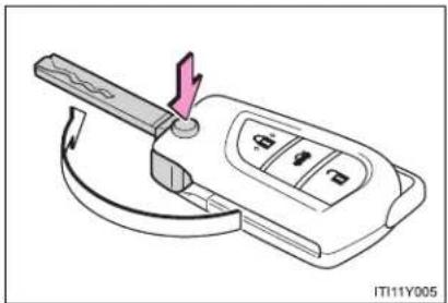
Diagram of a car key with a handle and control panel, showing no text or symbolsPress the button to open the key.
To stow, press the button then fold the key.
1-1. Key information
- When required to leave a key to the vehicle with a parking attendant (for right-hand drive vehicles with smart entry & start system)
Lock the glove box. (→P. 482)
Remove the mechanical key for your own use and provide the attendant with the electronic key only.
■ Key number plate
Keep the plate in a safe place such as your wallet, not in the vehicle. In the event that a key is lost, a new key can be made by any authorized Toyota dealer or repairer, or another duly qualified and equipped professional, using the key number plate. (→P. 699)
■ When riding in an aircraft
When bringing a key onto an aircraft, make sure you do not press any buttons on the key while inside the aircraft cabin. If you are carrying a key in your bag etc., ensure that the buttons are not likely to be pressed accidentally. Pressing a button may cause the key to emit radio waves that could interfere with the operation of the aircraft.

NOTICE
■ To prevent key damage
- Do not subject the keys to strong shocks, expose them to high temperatures by placing them in direct sunlight, or get them wet.
- Do not expose the keys to electromagnetic materials or attach any material that blocks electromagnetic waves to the key surface.
Do not disassemble the key.
1-2. Opening, closing and locking the doors
Smart entry & start system\*
The following operations can be performed simply by carrying the electronic key on your person, for example in your pocket. (The driver should always carry the electronic key.)
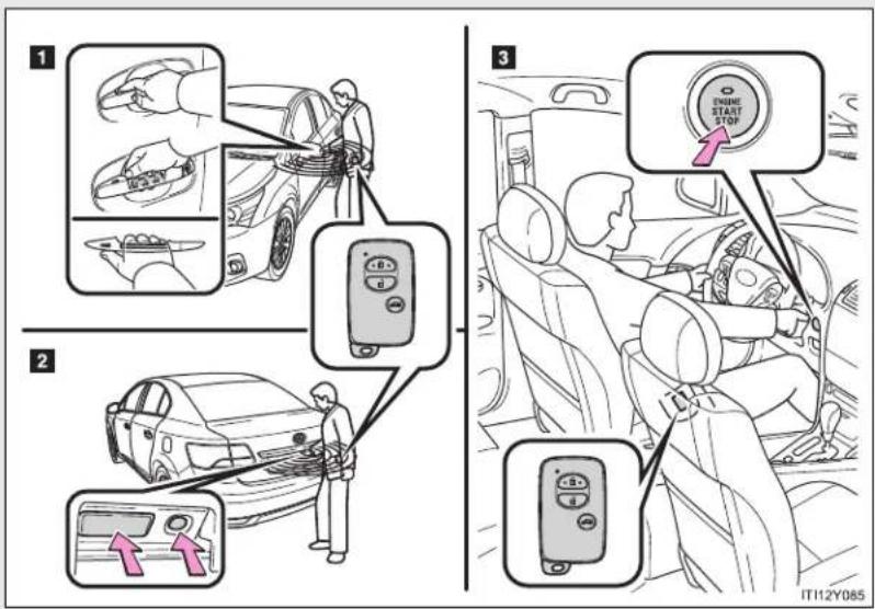
text_image
Diagram illustrating car safety instructions with labeled steps and icons for cleaning, switching, and stop controls.1 Unlocks and locks the doors and trunk/back door ( P. 40)
2 Unlocks and locks the trunk/back door (→P. 40)
3 Starts and stops the engine ( P. 210)
*: If equipped
1-2. Opening, closing and locking the doors
Unlocking and locking the doors and trunk/back door (front door handles only)
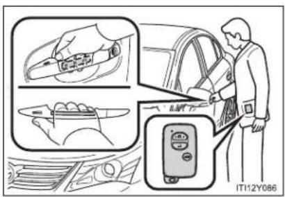
text_image
IT112Y086Grip the handle to unlock.
Make sure to touch the sensor on the back of the handle.
The doors and trunk/back door cannot be unlocked for 3 seconds after they are locked.

text_image
Diagram illustrating car seatbelt usage with magnified inset showing hand positioning and control panelTouch the sensor area to lock.
Unlocking and locking the trunk/back door

text_image
ITN12Y013Press the unlock button to unlock.
Lock the trunk/back door again when you leave the vehicle. They will not lock automatically after they have been opened and then closed.
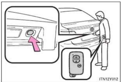
text_image
ITN12Y012Press the lock button to lock.
Antenna location and effective range
Antenna location
▶ Sedan
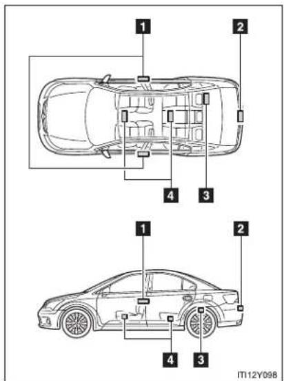
text_image
1 2 4 3 1 2 4 3 IT12Y0981 Antennas outside cabin
2 Antenna outside trunk
3 Antenna inside trunk
4 Antennas inside cabin
1-2. Opening, closing and locking the doors
Wagon
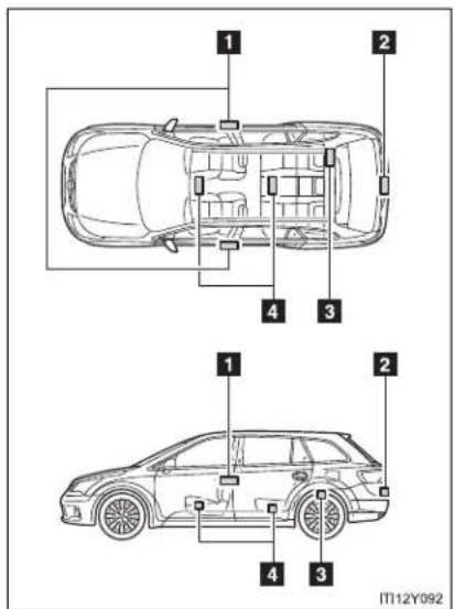
text_image
1 2 4 3 1 2 4 3 IT12Y0921 Antennas outside cabin
2 Antenna outside luggage compartment
3 Antenna inside luggage compartment
4 Antennas inside cabin
■ Effective range (areas within which the electronic key is detected)
▶ Sedan
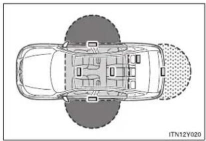
natural_image
Top-down schematic of a car showing interior layout and seatbelt pattern (no text or symbols)Wagon
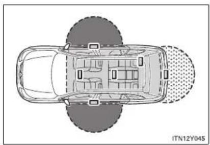
natural_image
Top-down schematic of a car showing front, rear, and side views with no text or symbolsWhen locking or unlocking the side doors
The system can be operated when the electronic key is within about 0.7 m (2.3 ft.) of either of the outside front door handles.
When starting the engine or changing "ENGINE START STOP" switch modes
The system can be operated when the electronic key is inside the vehicle.
When locking or unlocking the trunk/back door
The system can be operated when the electronic key is within about 0.7 m (2.3 ft.) of the trunk/back door opener switch.
Operation signals
The emergency flashers flash to indicate that the doors and trunk/back door have been locked/unlocked. (Locked: Once; Unlocked: Twice)
■ When the door cannot be locked using the topside sensor area

natural_image
Illustration of a hand holding a pen or stylus, no text or symbols presentIf the door will not lock even when the topside sensor area is touched, try touching both the topside and underside sensor areas at the same time.
■ Conditions affecting operation
The smart entry & start system uses weak radio waves. In the following situations, the communication between the electronic key and the vehicle may be affected, preventing the smart entry & start system and wireless remote control from operating properly. (Ways of coping: →P. 702)
- When the electronic key battery is depleted
- Near a TV tower, electric power plant, gas station, radio station, large display, airport or other facility that generates strong radio waves or electrical noise
- When carrying a portable radio, cellular phone, cordless phone or other wireless communication devices
- When the electronic key is in contact with, or is covered by the following metallic objects
- Cards to which aluminum foil is attached
• Cigarette boxes that have aluminum foil inside
• Metallic wallets or bags -
Coins
• Hand warmers made of metal
• Media such as CDs and DVDs -
When multiple electronic keys are in the vicinity
- When another wireless key (that emits radio waves) is being used nearby
-
When carrying or using the electronic key together with the following devices that emit radio waves
-
Another vehicle's electronic key or a wireless key that emits radio waves
- Personal computer or personal digital assistants (PDAs)
• Digital audio players - Portable game systems
- If window tint with a metallic content or metallic objects are attached to the rear window
- Sedan: If a metallic object is placed on the package tray
Battery-saving function
In the following circumstances, the smart entry & start system is disabled in order to prevent the vehicle and electronic key batteries from discharging.
- When the smart entry & start system has not been used for 5 days or more
- When the electronic key has been left within approximately 1 m (3 ft.) of the vehicle for 10 minutes or more
The system will resume operation when...
- The vehicle is locked touching the door handle lock sensor area.
- The vehicle is locked/unlocked using the wireless remote control function (→P. 62) or the mechanical key. (→P. 702)
1-2. Opening, closing and locking the doors
Electronic key battery depletion
- The standard battery life is 1 to 2 years. (The battery becomes depleted even if the electronic key is not used.) If the smart entry & start system or the wireless remote control function does not operate, or the detection area becomes smaller, the battery may be depleted. Replace the battery when necessary. ( P. 564)
- If the battery becomes low, an alarm will sound in the cabin when the engine stops. (→P. 48)
- To avoid serious deterioration, do not leave the electronic key within 1 m (3 ft.) of the following electrical appliances that produce a magnetic field:
• TVs
• Personal computers
- Cellular phones, cordless phones and battery chargers
- Recharging cellular phones or cordless phones
- Glass top ranges
- Table lamps
■ To operate the system properly
Make sure to carry the electronic key when operating the system. Do not get the electronic key too close to the vehicle when operating the system from the outside of the vehicle.
Depending on the position and holding condition of the electronic key, the key may not be detected correctly and the system may not operate properly. (The alarm may go off accidentally, or the door lock prevention may not function.)
Note for the smart entry & start system
- Even when the electronic key is within the effective range (detection areas), the system may not operate properly in the following cases.
- The electronic key is too close to the window or outside door handle, near the ground, or in a high place when the doors are locked or unlocked.
- The electronic key is near the ground or in a high place, or too close to the rear bumper center when the trunk or back door is locked/unlocked.
- The electronic key is on the instrument panel, package tray (sedan), luggage cover (wagon), floor or in the glove box when the engine is started or “ENGINE START STOP” switch modes are changed.
- Do not leave the electronic key on top of the instrument panel or near the door pockets when exiting the vehicle. Depending on the radio wave reception conditions, it may be detected by the antenna outside the cabin and the door will become lockable from the outside, possibly trapping the electronic key inside the vehicle.
- As long as the electronic key is within the effective range, the doors may be locked or unlocked by anyone.
- Even if the electronic key is not inside the vehicle, it may be possible to start the engine if the electronic key is near the window.
- The doors may unlock or lock if a large amount of water splashes on the door handle, such as in the rain or in a car wash when the electronic key is within the effective range. (The doors will automatically be locked after approximately 30 seconds if the doors are not opened and closed.)
- If the key is kept near the vehicle while it is being washed, water applied to a door handle may cause the door to lock and unlock repeatedly. In this event, place the key in a location 2 m (6 ft.) or more from the vehicle, taking care not to lose the key.
- If the key is inside the vehicle while it is being washed, water applied to a door handle may cause a buzzer to sound and a message to be displayed. In this event, locking all doors will cause the message to extinguish and the buzzer to stop sounding.
1-2. Opening, closing and locking the doors
- It may not be possible to lock the doors if the sensor area is covered by mud, ice, snow etc. In this event, try locking again after cleaning the area, or lock by touching the sensor area on the underside of the door handle.
- Gripping the door handle when wearing a glove may not unlock or lock the door.
- If the wireless remote control is used to lock the doors when the electronic key is near the vehicle, there is a possibility that the door may not be unlocked by the smart entry & start system. (Use the wireless remote control to unlock the doors.)
- A sudden approach to the effective range or door handle operation may prevent the doors from being unlocked. In this case, return the door handle to the original position and check that the doors unlock before pulling the door handle again.
- When the vehicle is not driven for extended periods
To prevent theft of the vehicle, do not leave the electronic key within 2 m (6 ft.) of the vehicle.
■ Security feature
If a door is not opened within approximately 30 seconds after the vehicle is unlocked, the security feature automatically locks the vehicle again.
■ Alarms and warning indicators
A combination of exterior and interior alarms are used to prevent theft of the vehicle and unforeseeable accidents resulting from erroneous operation. Take appropriate measures according to the warning message shown on the multi-information display. (→P. 624)
The following table describes circumstances and correction procedures when only alarms are sounded.
| Alarm Situation | Correction procedure | |
| Interior alarmpings once and exterior alarmsounds once for 10 seconds | Tried to lock the doors using the entry function while the electronic key is still inside the passenger compartment or trunk/luggage compartment | Retrieve the electronic key and lock the doors again |
| Tried to exit the vehicle and lock the doors without first turning the “ENGINE START STOP” switch OFF | Turn the “ENGINE START STOP” switch OFF and lock the doors again | |
| Exterior alarm sounds once for 10 seconds | Tried to lock the vehicle while a door, trunk or back door is open | Close all of the doors and lock the doors again |
| Interior alarmpings continuously | The “ENGINE START STOP” switch was turned to ACCESSORY mode while the driver's door was open (or the driver's door was opened while the “ENGINE START STOP” switch was in ACCESSORY mode) | Turn the “ENGINE START STOP” switch OFF and close the driver's door |
| The “ENGINE START STOP” switch was turned OFF while the driver's door was open | Close the driver's door |
1-2. Opening, closing and locking the doors
| Alarm Situation | Correction procedure | |
| Interior alarm sounds continuously | When the “ENGINE START STOP” switch is in IGNITION ON or ACCES-SORY mode, an attempt was made to open the door and exit the vehicle, and the shift lever was not in “P” | Shift the shift lever to “P” and turn the “ENGINE START STOP” switch OFF |
| Interior and exterior alarms sound continuously | When the “ENGINE START STOP” switch is in IGNITION ON or ACCES-SORY mode, the driver’s door was closed after the electronic key was carried outside the vehicle, and the shift lever was not in “P” | Shift the shift lever to “P”, turn the “ENGINE START STOP” switch OFF and close the driver’s door again |
| Interior alarm pings once | The electronic key battery is low | Replace the electronic key battery |
| Tried to start the engine without the electronic key being present, or the electronic key was not functioning normally | Start the engine with the electronic key present* | |
| Interior alarm pings once and exterior alarm sounds 3 times | The driver's door was closed after the electronic key was carried outside the vehicle, and the “ENGINE START STOP” switch was not turned OFF | Turn the “ENGINE START STOP” switch OFF and close the driver's door again |
| An occupant carried the electronic key outside the vehicle and closed the door while the “ENGINE START STOP” switch was not OFF | Bring the electronic key back into the vehicle |
*: If the engine does not start when the electronic key is inside the vehicle, the electronic key battery may be depleted or there may be difficulties receiving signal from the key. (→P. 703)
■ If the smart entry & start system does not operate properly
- Locking and unlocking the doors: Use the mechanical key. (→P. 702)
- Starting the engine: →P. 703
■ When the electronic key battery is fully depleted
→P. 564
■ Customization that can be configured at any authorized Toyota dealer or repairer, or another duly qualified and equipped professional
Settings (e.g. smart entry & start system) can be changed. (Customizable features → P. 749)
1-2. Opening, closing and locking the doors
■ Certification for the smart entry & start system
Hereby, Toyota Motor Corporation, declares that this TMLF8-9 is in compliance with the essential requirements and other relevant provisions of Directive 1999/5/EC.
TOYOTA
TOYOTA MOTOR CORPORATION
- TOYOTA-CHQ, TOYOTA, AICHI, 471-8571(Head Office) or 471-8572(Research & Development Group) JAPAN TEL: +81-565-28-2121
R&TTE Declaration of Conformity
We,
Manufacturer's Name: TOYOTA MOTOR CORPORATION
Manufacturer's Address: 1, Toyota -cho, Toyota, Aichi, 471-8572, Japan
hereby declare under our sole responsibility that the product:
Product Name: LF Oscillator
Product Model: TMLF8-9
to which this declaration relates is in conformity with the essential requirements and other relevant requirements of the R&TTE Directive (1999/5/EC). The product is compliant with the following standards and/or other normative documents:
-Health & safety requirements:
-EMC requirements
-Effective uses of radio spectrum:
EN60950-1
EN 301 489-01 & EN 301 489-03
EN 300 330-2
Supplementary information:
 |
Date:
May 16, 2008
Signature:
Jahashi Enonato
Takaaki Enomoto
| Hereby, Toyota Motor Corporation, declares that this TMLF8-9 is in compliance with the essential requirements and other relevant provisions of Directive 1999/5/EC. |
| Toyota Motor Corporation vakuuttaa täten että TMLF8-9 typpinen laite on direktiivin 1999/5/EY oleellisten vaatimusten ja sitä koskevien direktiivin muiden ehtojen mukainen. |
| Hierbij verklaart Toyota Motor Corporation dat het toestel TMLF8-9 in overeenstemming is met de essentiële eisen en de andere relevante bepalingen van richtlijn 1999/5/EG. |
| Par la présente Toyota Motor Corporation déclare que l'appareil TMLF8-9 est conforme aux exigences essentielles et aux autres dispositions pertinentes de la directive 1999/5/CE. |
| Härmed intygar Toyota Motor Corporation att denna TMLF8-9 står I överensstämmelse med de väsentliga egenskapskrav och övriga relevanta bestämmelser som framgår av direktiv 1999/5/EG. |
| Undertegnede Toyota Motor Corporation erklærer herved, at følgende udstyr TMLF8-9 overholder de väsentlige krav og øvrige relevante krav i direktiv 1999/5/EF. |
| Hiermit erklärt Toyota Motor Corporation, dass sich das Gerät TMLF8-9 in Übereinstimmung mit den grundlegenden Anforderungen und den übrigen einschlägigen Bestimmungen der Richtlinie 1999/5/EG befindet. |
| ME THN ΠΑΡΟΥΣΑ Toyota Motor Corporation ΔΗΛΩΝΕΙ ΟΤΙ TMLF8-9 ΣΥΜΜΟΡΦΩΝΕΤΑΙ ΠΡΟΣ ΤΙΣ ΟΥΣΙΩΔΕΙΣ ΑΠΑΙΤΗΣΕΙΣ ΚΑΙ ΤΙΣ ΛΟΙΠΕΣ ΣΧΕΤΙΚΕΣ ΔΙΑΤΑΞΕΙΣ ΤΗΣ ΟΔΗΓΙΑΣ 1999/5/EK. |
| Con la presente Toyota Motor Corporation dichiara che questo TMLF8-9 è conforme ai requisiti essenziali ed alle altre disposizioni pertinenti stabilite dalla direttiva 1999/5/CE. |
| Por medio de la presente Toyota Motor Corporation declara que el TMLF8-9 cumple con los requisitos esenciales y cualesquiera otras disposiciones aplicables o exigibles de la Directiva 1999/5/CE. |
| Toyota Motor Corporation declara que este TMLF8-9 está conforme com os requisitos essenciais e outras disposições da Directiva 1999/5/CE. |
| Hawnhekk, Toyota Motor Corporation, jiddikjara li dan TMLF8-9 jikkonforma mal-ħtigijiet essenzjali u ma provvedimenti oħrajn relevanti li hemm fid-Dirrettiva 1999/5/EC. |
| Käesolevaga kinnitab Toyota Motor Corporation seadme TMLF8-9 vastavust direktiivi 1999/5/EÜ põhinõuetele ja nimetatud direktiivist tulenevatele teistele asjakohastele sätetele. |
1-2. Opening, closing and locking the doors
| Alulírott, Toyota Motor Corporation nyilatkozom, hogy a TMLF8-9 megfelel a vonatkozó alapvető követelményeknek és az 1999/5/EC irányelv egyéb előírásainak. |
| Toyota Motor Corporation týmto vyhlasuje, že TMLF8-9 splňa základné požiadavky a všetky príslušné ustanovenia Smernice 1999/5/ES. |
| Toyota Motor Corporation tímto prohlašuje, že tento TMLF8-9 je ve shodě se základními požadavky a dalšími příslušnými ustanoveními směrnice 1999/5/ES. |
| Toyota Motor Corporation izjavlja, da je ta TMLF8-9 v skladu z bistvenimi zahtevami in ostalimi relevantními določili direktive 1999/5/ES. |
| Šiuo Toyota Motor Corporation deklaruoja, kad šis TMLF8-9 atitinka esminius reikalavimus ir kitas 1999/5/EB Direktyvos nuostatas. |
| Ar šo Toyota Motor Corporation deklarě, ka TMLF8-9 atbilst Direktivas 1999/5/EK bütiskajām prasībām un citiem ar to saistītajiem noteikumiem. |
| Niniejszym Toyota Motor Corporation oświadcza, že TMLF8-9 jest zgodny z zasadniczymi wymogami oraz pozostałymi stosownymi postanowieniami Dyrektywy 1999/5/EC. |
| Hér með lýsir Toyota Motor Corporation yfir því að TMLF8-9 er í samræmi við grunnkröfur og aðrar kröfur, sem gerðar eru í tilskipun 1999/5/EC. |
| Toyota Motor Corporation erklærer herved at utstyret TMLF8-9 er i samsvar med de grunnleggende krav og øvrige relevante krav i direktiv 1999/5/EF. |
| Ovim, Toyota Motor Corporation, izjavljuje da ovaj TMLF8-9 je usklađen sa bitnim zahtjevima i drugim relevantnim odredbama Direktive 1999/5/EC. |
Hereby, TRCZ s.r.o., declares that this B75EA is in compliance with the essential requirements and other relevant provisions of Directive 1999/5/EC.
TRCZ
R&TTE Declaration of Conformity
We,
Manufacturer's Name: TRCZ s.r.o.
Manufacturer's Address: Prumyslova 1165, 41002, Lovosice, Czech Republic
hereby declare under our sole responsibility that the product:
Product Name: Electronic Key
Product Model: B75EA
to which this declaration relates is in conformity with the essential requirements and other relevant requirements of the R&TTE Directive (1999/5/EC). The product is compliant with the following standards and/or other normative documents:
Safety: EN80950-1
EMC: EN301 489-1 & -3
Spectrum: EN300 220-2, EN300 330-2
Supplementary information:
| * CE mark | CE |
| * Member states intended for use | EU and EFTA |
| * Member states with restrictive use | None |
Date:
Signature:
Position of the signatory:
26 March 2008

Ikuzo Kojima
President
1-2. Opening, closing and locking the doors
| Hereby, TRCZ s.r.o., declares that this B75EA is in compliance with the essential requirements and other relevant provisions of Directive 1999/5/EC. |
| TRCZ s.r.o. vakuuttaa täten että B75EA tyyppinen laite on direktiivin 1999/5/EY oleellisten vaatimusten ja sitä koskevien direktiivin muiden ehtojen mukainen. |
| Hierbij verklaart TRCZ s.r.o. dat het toestel B75EA in overeenstemming is met de essentiële eisen en de andere relevante bepalingen van richtlijn 1999/5/EG. |
| Par la présente TRCZ s.r.o. déclare que l'appareil B75EA est conforme aux exigences essentielles et aux autres dispositions pertinentes de la directive 1999/5/CE. |
| Härmed intygar TRCZ s.r.o. att denna B75EA står I överensstämmelse med de väsentliga egenskapskrav och övriga relevanta bestämmelser som framgår av direktiv 1999/5/EG. |
| Undertegnede TRCZ s.r.o. erklærer herved, at fölgende udstyr B75EA overholder de väsentlige krav og øvrige relevante krav i direktiv 1999/5/EF. |
| Hiermit erklärt TRCZ s.r.o., dass sich das Gerät B75EA in Übereinstimmung mit den grundlegenden Anforderungen und den übrigen einschlägigen Bestimmungen der Richtlinie 1999/5/EG befindet. |
| ME THN ΠΑΡΟΥΣΑ TRCZ s.r.o. ΔΗΛΩΝΕΙ ΟΤΙ B75EA ΣΥΜΜΟΡΦΩΝΕΤΑΙ ΠΡΟΣ ΤΙΣ ΟΥΣΙΩΔΕΙΣ ΑΠΑΙΤΗΣΕΙΣ ΚΑΙ ΤΙΣ ΛΟΙΠΕΣ ΣΧΕΤΙΚΕΣ ΔΙΑΤΑΞΕΙΣ ΤΗΣ ΟΔΗΓΙΑΣ 1999/5/ΕΚ. |
| Con la presente TRCZ s.r.o. dichiara che questo B75EA è conforme ai requisiti essenziali ed alle altre disposizioni pertinenti stabilite dalla direttiva 1999/5/CE. |
| Por medio de la presente TRCZ s.r.o. declara que el B75EA cumple con los requisitos esenciales y cualesquiera otras disposiciones aplicables o exigibles de la Directiva 1999/5/CE. |
| TRCZ s.r.o. declara que este B75EA está conforme com os requisitos essenciais e outras disposições da Directiva 1999/5/CE. |
| Hawnhekk, TRCZ s.r.o., jiddikjara li dan B75EA jikkonforma mal-ħtigijiet essenzjali u ma provvedimenti oħrajn relevanti li hemm fid-Dirrettiva 1999/5/EC. |
| Käesolevaga kinnitab TRCZ s.r.o. seadme B75EA vastavust direktiivi 1999/5/EÜ põhinõuetele ja nimetatud direktiivist tulenevatele teistele asjakohastele sätetele. |
| Alulírott, TRCZ s.r.o. nyilatkozom, hogy a B75EA megfelel a vonatkozó alapvetõ követelményeknek és az 1999/5/EC irányelv egyéb előírásainak. |
| TRCZ s.r.o. týmto vyhlasuje, že B75EA splňa základné požiadavky a všetky príslušné ustanovenia Smernice 1999/5/ES. |
| TRCZ s.r.o. tímto prohlašuje, že tento B75EA je ve shodě se základními požadavky a dalšími příslušnými ustanoveními směrnice 1999/5/ES. |
| TRCZ s.r.o. izjavlja, da je ta B75EA v skladu z bistveními zahtevami in ostalimi relevantními določili direktive 1999/5/ES. |
| Šiuo TRCZ s.r.o. deklaruoja, kad šis B75EA atitinka esminius reikalavimus ir kitas 1999/5/EB Direktyvos nuostatas. |
| Ar šo TRCZ s.r.o. deklarē, ka B75EA atbilst Direktīvas 1999/5/EK būtiskajām prasībām un citiem ar to saistītajiem noteikumiem. |
| Niniejszym TRCZ s.r.o. oświadcza, že B75EA jest zgodny z zasadniczymi wymogami oraz pozostałymi stosownymi postanowieniami Dyrektywy 1999/5/EC. |
| Hér með lýsir TRCZ s.r.o. yfir því að B75EA er í samræmi við grunnkröfur og aðrar kröfur, sem gerðar eru í tilskipun 1999/5/EC. |
| TRCZ s.r.o. erklærer herved at utsyret B75EA er i samsvar med de grunnleggende krav og øvrige relevante krav i direktiv 1999/5/EF. |
| Ovim, TRCZ s.r.o., izjavljuje da ovaj B75EA je usklađen sa bitnim zahtjevima i drugim relevantním odredbama Direktive 1999/5/EC. |
1-2. Opening, closing and locking the doors
Hereby, TRCZ s.r.o., declares that this B76UA is in compliance with the essential requirements and other relevant provisions of Directive 1999/5/EC.
TRCZ
R&TTE Declaration of Conformity
We,
Manufacturer's Name: TRCZ s.r.o.
Manufacturer's Address: Prumyslova 1165, 41002, Lovosice, Czech Republic
hereby declare under our sole responsibility that the product:
Product Name: Tuner
Product Model: B76UA
to which this declaration relates is in conformity with the essential requirements and other relevant requirements of the R&TTE Directive (1999/5/EC). The product is compliant with the following standards and/or other normative documents:
Safety: EN60950-1
EMC: EN301 489-1 & -3
Spectrum: EN300 220-2
Supplementary information:
| * CE mark | CE |
| * Member states intended for use | EU and EFTA |
| * Member states with restrictive use | None |
Date:
Signature:
Position of the signatory:
29 February 2008

| Hereby, TRCZ s.r.o., declares that this B76UA is in compliance with the essential requirements and other relevant provisions of Directive 1999/5/EC. |
| TRCZ s.r.o. vakuuttaa täten että B76UA tyyppinen laite on direktiivin 1999/5/EY oleellisten vaatimusten ja sitä koskevien direktiivin muiden ehtojen mukainen. |
| Hierbij verklaart TRCZ s.r.o. dat het toestel B76UA in overeenstemming is met de essentiële eisen en de andere relevante bepalingen van richtlijn 1999/5/EG. |
| Par la présente TRCZ s.r.o. déclare que l'appareil B76UA est conforme aux exigences essentielles et aux autres dispositions pertinentes de la directive 1999/5/CE. |
| Härmed intygar TRCZ s.r.o. att denna B76UA står I överensstämmelse med de väsentliga egenskapskrav och övriga relevanta bestämmelser som framgår av direktiv 1999/5/EG. |
| Undertegnede TRCZ s.r.o. erklærer herved, at fölgende udstyr B76UA overholder de väsentlige krav og øvrige relevante krav i direktiv 1999/5/EF. |
| Hiermit erklärt TRCZ s.r.o., dass sich das Gerät B76UA in Übereinstimmung mit den grundlegenden Anforderungen und den übrigen einschlägigen Bestimmungen der Richtlinie 1999/5/EG befindet. |
| ME THN ΠΑΡΟΥΣΑ TRCZ s.r.o. ΔΗΛΩΝΕΙ ΟΤΙ B76UA ΣΥΜΜΟΡΦΩΝΕΤΑΙ ΠΡΟΣ ΤΙΣ ΟΥΣΙΩΔΕΙΣ ΑΠΑΙΤΗΣΕΙΣ ΚΑΙ ΤΙΣ ΛΟΙΠΕΣ ΣΧΕΤΙΚΕΣ ΔΙΑΤΑΞΕΙΣ ΤΗΣ ΟΔΗΓΙΑΣ 1999/5/ΕΚ. |
| Con la presente TRCZ s.r.o. dichiara che questo B76UA è conforme ai requisiti essenziali ed alle altre disposizioni pertinenti stabilite dalla direttiva 1999/5/CE. |
| Por medio de la presente TRCZ s.r.o. declara que el B76UA cumple con los requisitos esenciales y cualesquiera otras disposiciones aplicables o exigibles de la Directiva 1999/5/CE. |
| TRCZ s.r.o. declara que este B76UA está conforme com os requisitos essenciais e outras disposições da Directiva 1999/5/CE. |
| Hawnhekk, TRCZ s.r.o., jiddikjara li dan B76UA jikkonforma mal-ħtiġijiet essenzjali u ma provvedimenti oħrajn relevanti li hemm fid-Dirrettiva 1999/5/EC. |
1-2. Opening, closing and locking the doors
■ Caution regarding interference with electronic devices
- People with implanted pacemakers or cardiac defibrillators should maintain a reasonable distance between themselves and the smart entry & start system antennas. (→P. 41)
The radio waves may affect the operation of such devices. If necessary, the entry function can be disabled. Ask any authorized Toyota dealer or repairer, or another duly qualified and equipped professional for details, such as the frequency of radio waves and timing of emitting the radio waves. Then, consult your doctor to see if you should disable the entry function.
- Users of any electrical medical device other than implanted pacemakers and implanted cardiac defibrillators should consult the manufacturer of the device for information about its operation under the influence of radio waves.
Radio waves could have unexpected effects on the operation of such medical devices.
Ask any authorized Toyota dealer or repairer, or another duly qualified and equipped professional for details for disabling the entry function.
1-2. Opening, closing and locking the doors
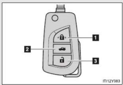
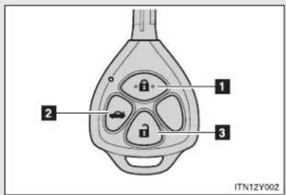
Wireless remote control
The wireless remote control can be used to lock and unlock the vehicle from outside the vehicle.
▶ Vehicles with smart entry & start system

text_image
1 2 3 ITN12Y0011 Locks all doors and trunk/back door
2 Unlocks all doors and trunk/back door
3 Unlocks the trunk/back door
Lock the trunk/back door again when you leave the vehicle. They will not lock automatically after they have been opened and then closed.
▶ Vehicles without smart entry & start system
Type A
text_image
1 2 3 IT12Y0831 Locks all doors and trunk/back door
2 Unlocks the trunk/back door Lock the trunk/back door again when you leave the vehicle. They will not lock automatically after they have been opened and then closed.
3 Unlocks all doors and trunk/back door
Type B
text_image
1 2 3 ITN12Y0021 Locks all doors and trunk/back door
2 Unlocks the trunk/back door Lock the trunk/back door again when you leave the vehicle. They will not lock automatically after they have been opened and then closed.
3 Unlocks all doors and trunk/back door
Operation signals
The emergency flashers flash to indicate that the doors and trunk/back door have been locked/unlocked. (Locked: Once; Unlocked: Twice)
■ Door lock buzzer (vehicles with smart entry & start system)
If the door, trunk or back door is not fully closed, a buzzer sounds continuously for 10 seconds if an attempt to lock the door is made. Fully close the door to stop the buzzer, and lock the vehicle once more.
Alarm
Using the wireless remote control to lock the doors will set the alarm system.
■ Key battery depletion
▶ Vehicles with smart entry & start system →P. 46
▶ Vehicles without smart entry & start system If the wireless remote control function does not operate, the battery may be depleted. Replace the battery when necessary. (→P. 565)
Security feature
If a door is not opened within approximately 30 seconds after the vehicle is unlocked, the security feature automatically locks the vehicle again.
■ If the wireless remote control does not operate properly
▶ Vehicles with smart entry & start system
- Locking and unlocking the doors: Use the key. (→P. 702)
● Starting the engine: →P. 703
▶ Vehicles without smart entry & start system
Locking and unlocking the doors: Use the key. (→P. 78)
■ When the electronic key battery is fully depleted
→P. 564
■ Conditions affecting operation
▶ Vehicles with smart entry & start system
$$ \rightarrow \mathrm{P}. 4 4 $$
▶ Vehicles without smart entry & start system
The wireless remote control function may not operate normally in the following situations.
- Near a TV tower, radio station, electric power plant, airport or other facility that generates strong radio waves
- When carrying a portable radio, cellular phone or other wireless communication device
- When multiple wireless keys are in the vicinity
- When the wireless key has come into contact with, or is covered by a metallic object
- When a wireless key (that emits radio waves) is being used nearby
- When the wireless key has been left near an electrical appliance such as a personal computer
- When the wireless key battery is depleted
- If window tint with a metallic content or metallic objects are attached to the rear window
- Sedan: If a metallic object is placed on the package tray
■ Customization that can be configured at any authorized Toyota dealer or repairer, or another duly qualified and equipped professional
Settings (e.g. door lock buzzer) can be changed.
(Customizable features → P. 749)
1-2. Opening, closing and locking the doors
■ Certification for wireless remote control (vehicles without smart entry & start system)
▶ Type A
Valeo
Valeo Security Systems
R&TTE Declaration of Conformity
We.
Manufacturer's name: Valeo Security Systems
Manufacturer's address: 76, rue Auguste Perret
F-96046 Créteil - France
hereby declare under our sole responsibility that the product:
Product name:
Model No:
RF Transmitter (Jack Knife Key)
A03TAA
to which this declaration relates, complies with the essential protection requirements of R&TTE Directive (1999/5/EC). The product is compliant with the following standards and/or normative documents:
- Radio matters: EN 300 220-1 V2.3.1 (2010-02), EN 300 220-2 V2.3.1 (2010-02)
- EMC: EN 301 489-1 V1.8.1 (2008-04), EN 301 489-3 V1.4.1 (2002-06)
- Electrical Safety: EN 60950-1 (2006) /A11 (2009)/ A1 (2010)
CE marking:
C€0682
Signature:
J. Elugof
Approval Engineer
Date: 19-Apr-11
| Valeo Security Systems tímto prohlašuje, že tento A03TAA je ve shodě se základními požadavky a daišimi příslušnými ustanoveními směrnice 1999/5/ES. |
| Undertegnede Valeo Security Systems erklærer herved, at følgende udstyr A03TAA overholder de væsentlige krav og øvrige relevante krav i direktiv 1999/5/EF. |
| Hiermit erklärt Valeo Security Systems , dass sich das Gerät A03TAA in Übereinstimmung mit den grundlegenden Anforderungen und den übrigen einschlägigen Bestimmungen der Richtlinie 1999/5/EG befindet. |
| Käesolevaga kinnitab Valeo Security Systems seadme A03TAA vastavust direktiivi 1999/5/EÜ põhinõuetele ja nimetatud direktiivist tulenevatele teistele asjakohastele sätetele. |
| Hereby, Valeo Security Systems declares that this A03TAA is in compliance with the essential requirements and other relevant provisions of Directive 1999/5/EC. |
| Por medio de la presente Valeo Security Systems declara que A03TAA cumple con los requisitos esenciales y cualesquiera otras disposiciones aplicables o exigibles de la Directiva 1999/5/CE. |
| ME THN ΠΑΡΟΥΣΑ Valeo Security Systems ΔΗΛΩΝΕΙ ΟΤΙ Α03TAA ΣΥΜΜΟΡΦΩΝΕΤΑΙ ΠΡΟΣ ΤΙΣ ΟΥΣΙΩΔΕΙΣ ΑΠΑΙΤΗΣΕΙΣ ΚΑΙ ΤΙΣ ΛΟΙΠΕΣ ΣΧΕΤΙΚΕΣ ΔΙΑΤΑΞΕΙΣ ΤΗΣ ΟΔΗΓΙΑΣ 1999/5/EK. |
| Par la présente Valeo Security Systems déclare que les appareils A03TAA sont conformes aux exigences essentielles et aux autres dispositions pertinentes de la directive 1999/5/CE. |
| Con la presente Valeo Security Systems dichiara che questo A03TAA è conforme ai requisiti essenziali ed alle altre disposizioni pertinenti stabilite dalla direttiva 1999/5/CE. |
| Ar šo Valeo Security Systems deklarē, ka A03TAA atbilst Direktīvas 1999/5/EK būtiskajām prasībām un citiem ar to saisītājiem noteikumiem. |
| Šiuo Valeo Security Systems deklaruoja, kad šis A03TAA atitinka esminius reikalavimus ir kitas 1999/5/EB Direktyvos nuostatas. |
| Hierbij verklaart Valeo Security Systems dat het toestel A03TAA in overeenstemming is met de essentiële eisen en de andere relevante bepalingen van richtlijn 1999/5/EG. |
1-2. Opening, closing and locking the doors
| Hawnhekk, Valeo Security Systems , jiddikjara li dan A03TAA jikkonforma malhtiğijiet essenzjali u ma provvedimenti oħrajn relevanti li hemm fid-Dirrettiva 1999/5/EC. |
| Alulírott, Valeo Security Systems nyilatkozom, hogy a A03TAA megfelel a vonatkozó alapvető követelményeknek és az 1999/5/EC irányelv egyéb előírásainak. |
| Niniejszym Valeo Security Systems oświadcza, że A03TAA jest zgodny z zasadniczymi wymogami oraz pozostałymi stosownymi postanowieniami Dyrektywy 1999/5/EC. |
| Valeo Security Systems declara que este A03TAA está conforme com os requisitos essenciais e outras disposições da Directiva 1999/5/CE. |
| Valeo Security Systems izjavlja, da je ta A03TAA v skladu z bistvenimi zahtevami in ostalimi relevantnimi določili direktive 1999/5/ES. |
| Valeo Security Systems týmto vyhlasuje, že A03TAA splňa základné požiadavky a všetky prislušné ustanovenia Smernice 1999/5/ES. |
| Valeo Security Systems vakuuttaa täten että A03TAA tyyppinen laite on direktiivin 1999/5/EY oleellisten vaatimusten ja sită koskevien direktiivin muiden ehtojen mukainen. |
| Härmed intygar Valeo Security Systems att denna A03TAA står l överensstämmelse med de väsentliga egenskapskrav och övriga relevanta bestämmelser som framgår av direktiv 1999/5/EG. |
| Hér með lýsir Valeo Security Systems yfir því að A03TAA er í samræmi við grunnkröfur og aðrar kröfur, sem gerðar eru í tilskipun 1999/5/EC. |
| Valeo Security Systems erklærer herved at utstyret A03TAA er i samsvar med de grunnleggende krav og øvrige relevante krav i direktiv 1999/5/EF. |
| Ovim , Valeo Security Systems, izjavljuje da ovaj A03TAA je usklađen sa bitnim zahtjevima i drugim relevantnim odredbama Direktive 1999/5/EC. |
Valeo
Valeo Security Systems
R&TTE Declaration of Conformity
We.
Manufacturer's name: Manufacturer's address:
Valeo Security Systems
- rue Auguste Perret
F-96046 Créteil - France
hereby declare under our sole responsibility that the product:
Product name
RF Receiver
Model No.:
060381-A
to which
to which
- Radio matters:
- FMC
- Electrical Safety:
EN 300 220-1 V2.1.1 (20
EN 301 489-1 V16.1 (2
EN 60950-1 (2002)
CE mark
(二)交易价格

Signatur
•
1
J. Hugot
Approva

Date: 20-Apr-11
1
表决结果:
69
(No text)
[Non-Text]
[Non-Text]
[Non-Text]
[Non-Text]
[Non-Text]
[Non-Text]
[Non-Text]
[Non-Text]
[Non-Text]
[Non-Text]
[Non-Text]
[Non-Text]
[Non-Text]
[Non-Text]
[Non-Text]
[Non-Text]
[Non-Text]
[Non-Text]
[Non-Text]
[Non-Text]
[Non-Text]
[Non-Text]
[Non-Text]
[Non-Text]
[Non-Text]
[Non-Text]
[Non-Text]
[Non-Text]
[Non-Text]
[Non-Text]
[Non-Text]
[Non-Text]
[Non-Text]
AVENSIS_EE (OM20B44E)
单位:元
[Non-Text]
[Non-Text]
[Non-Text]
[Non-Text]
[Non-Text]
[Non-Text]
[Non-Text]
[Non-Text]
[Non-Text]
[Non-Text]
[Non-Text]
[Non-Text]
[Non-Text]
[Non-Text]
[Non-Text]
[Non-Text]
[Non-Text]
[Non-Text]
[Non-Text]
1-2. Opening, closing and locking the doors
| Valeo Security Systems tímto prohlašuje, že tento 0603B1-A je ve shodě se základními požadavky a dalšími příslušnými ustanoveními směrnice 1999/5/ES. |
| Undertegnede Valeo Security Systems erklærer herved, at følgende udstyr 0603B1-A overholder de væsentlige krav og øvrige relevante krav i direktiv 1999/5/EF. |
| Hiermit erklärt Valeo Security Systems , dass sich das Gerät 0603B1-A in Übereinstimmung mit den grundlegenden Anforderungen und den übrigen einschlägigen Bestimmungen der Richtlinie 1999/5/EG befindet. |
| Käesolevaga kinnitab Valeo Security Systems seadme 0603B1-A vastavust direktiivi 1999/5/EÜ põhinõuetele ja nimetatud direktiivist tulenevatele teistele asjakohastele sätetele. |
| Hereby, Valeo Security Systems declares that this 0603B1-A is in compliance with the essential requirements and other relevant provisions of Directive 1999/5/EC. |
| Por medio de la presente Valeo Security Systems declara que 0603B1-A cumple con los requisitos esenciales y cualesquiera otras disposiciones aplicables o exigibles de la Directiva 1999/5/CE. |
| ME THN ΠΑΡΟΥΣΑ Valeo Security Systems ΔΗΛΩΝΕΙ ΟΤΙ 0603B1-A ΣΥΜΜΟΡΦΩΝΕΤΑΙ ΠΡΟΣ ΤΙΣ ΟΥΣΙΩΔΕΙΣ ΑΠΑΙΤΗΣΕΙΣ ΚΑΙ ΤΙΣ ΛΟΙΠΕΣ ΣΧΕΤΙΚΕΣ ΔΙΑΤΑΞΕΙΣ ΤΗΣ ΟΔΗΓΙΑΣ 1999/5/EK. |
| Par la présente Valeo Security Systems déclare que les appareils 0603B1-A sont conformes aux exigences essentielles et aux autres dispositions pertinentes de la directive 1999/5/CE. |
| Con la presente Valeo Security Systems dichiara che questo 0603B1-A è conforme ai requisiti essenziali ed alle altre disposizioni pertinenti stabilite dalla direttiva 1999/5/CE. |
| Ar šo Valeo Security Systems deklarē, ka 0603B1-A atbilst Direktīvas 1999/5/EK būtiskajām prasībām un citiem ar to saisītājiem noteikumiem. |
| Šiuo Valeo Security Systems deklaruoja, kad šis 0603B1-A atitinka esminius reikalavimus ir kitas 1999/5/EB Direktyvos nuostatas. |
| Hierbij verklaart Valeo Security Systems dat het toestel 0603B1-A in overeenstemming is met de essentiële eisen en de andere relevante bepalingen van richtlijn 1999/5/EG. |
| Hawnhekk, Valeo Security Systems , jiddikjara li dan 0603B1-A jikkonforma malhtigijiet essenzjali u ma provvedimenti ohrajn relevanti li hemm fid-Dirrettiva 1999/5/EC. |
| Alulírott, Valeo Security Systems nyilatkozom, hogy a 0603B1-A megfelel a vonatkozó alapvető követelményeknek és az 1999/5/EC irányelv egyéb előírásainak. |
| Niniejszym Valeo Security Systems oświadcza, że 0603B1-A jest zgodny z zasadniczymi wymogami oraz pozostałymi stosownymi postanowieniami Dyrektywy 1999/5/EC. |
| Valeo Security Systems declara que este 0603B1-A está conforme com os requisitos essenciais e outras disposições da Directiva 1999/5/CE. |
| Valeo Security Systems izjavlja, da je ta 0603B1-A v skladu z bistvenimi zahtevami in ostalimi relevantnimi določili direktive 1999/5/ES. |
| Valeo Security Systems týmto vyhlasuje, že 0603B1-A splňa základné požiadavky a všetky príslušné ustanovenia Smernice 1999/5/ES. |
| Valeo Security Systems vakuuttaa täten että 0603B1-A tyyppinen laite on direktiivin 1999/5/EY oleellisten vaatimusten ja sitä koskevien direktiivin muiden ehtojen mukainen. |
| Härmed intygar Valeo Security Systems att denna 0603B1-A står l överensstämmelse med de väsentliga egenskapskrav och övriga relevanta bestämmelser som framgår av direktiv 1999/5/EG. |
| Hér með lýsir Valeo Security Systems yfir pví að 0603B1-A er í samræmi við grunnkröfur og aðrar kröfur, sem gerðar eru í tilskipun 1999/5/EC. |
| Valeo Security Systems erklærer herved at utstyret 0603B1-A er i samsvar med de grunnleggende krav og øvrige relevante krav i direktiv 1999/5/EF. |
| Ovim , Valeo Security Systems, izjavljuje da ovaj 0603B1-A je usklađen sa bitnim zahtjevima i drugim relevantnim odredbama Direktive 1999/5/EC. |
1-2. Opening, closing and locking the doors
▶ Type B

R&TTE Declaration of Conformity
We,
Manufacturer's name:
Manufacturer's address:
hereby declare under our sole responsibility that the product:
- Product name:
Transmitter
- Model No.:
0603A1-A
to which this declaration relates, comply with the essential protection requirements of R&TTF Directive (1999/5/FC). The product is compliant with the following standards and/or normative documents:
- Radio matters:
EN 300 220-1 &-3 VI.1.1 (2000-09)
- FMC:
EN 301 489-1 (2005) & -3 (2002)
- Electrical Safety:
EN 60950-1 (2002)
CE marking

Date: 17/April 2008

| Valeo Securité Habitacle tímto prohlašuje, že tento 0603A1-A je ve shodě se základními požadavky a dalšími příslušnými ustanoveními směrnice 1999/5/ES. |
| Undertegnede Valeo Securité Habitacle erklærer herved, at følgende udstyr 0603A1-A overholder de væsentlige krav og øvrige relevante krav i direktiv 1999/5/EF. |
| Hiermit erklärt Valeo Securité Habitacle , dass sich das Gerät 0603A1-A in Übereinstimmung mit den grundlegenden Anforderungen und den übrigen einschlägigen Bestimmungen der Richtlinie 1999/5/EG befindet. |
| Käesolevaga kinnitab Valeo Securité Habitacle seadme 0603A1-A vastavust direktiivi 1999/5/EÜ põhinõuetele ja nimetatud direktiivist tulenevatele teistele asjakohastele sätetele. |
| Hereby, Valeo Securité Habitacle declares that this 0603A1-A is in compliance with the essential requirements and other relevant provisions of Directive 1999/5/EC. |
| Por medio de la presente Valeo Securité Habitacle declara que 0603A1-A cumple con los requisitos esenciales y cualesquiera otras disposiciones aplicables o exigibles de la Directiva 1999/5/CE. |
| ME THN ΠΑΡΟΥΣΑ Valeo Securité Habitacle ΔΗΛΩΝΕΙ ΟΤΙ 0603A1-A ΣΥΜΜΟΡΦΩΝΕΤΑΙ ΠΡΟΣ ΤΙΣ ΟΥΣΙΩΔΕΙΣ ΑΠΑΙΤΗΣΕΙΣ ΚΑΙ ΤΙΣ ΛΟΙΠΕΣ ΣΧΕΤΙΚΕΣ ΔΙΑΤΑΞΕΙΣ ΤΗΣ ΟΔΗΓΙΑΣ 1999/5/EK. |
| Par la présente Valeo Securité Habitacle déclare que les appareils 0603A1-A sont conformes aux exigences essentielles et aux autres dispositions pertinentes de la directive 1999/5/CE. |
| Con la presente Valeo Securité Habitacle dichiara che questo 0603A1-A è conforme ai requisiti essenziali ed alle altre disposizioni pertinenti stabilite dalla direttiva 1999/5/CE. |
| Ar šo Valeo Securité Habitacle deklarē, ka 0603A1-A atbilst Direktīvas 1999/5/EK būtiskajām prasībām un citiem ar to saistītajiem noteikumiem. |
| Šiuo Valeo Securité Habitacle deklaruoja, kad šis 0603A1-A atitinka esminius reikalavimus ir kitas 1999/5/EB Direktyvos nuostatas. |
| Hierbij verklaart Valeo Securité Habitacle dat het toestel 0603A1-A in overeenstemming is met de essentiële eisen en de andere relevante bepalingen van richtlijn 1999/5/EG. |
1-2. Opening, closing and locking the doors
| Hawnhekk, Valeo Securité Habitacle , jiddikjara li dan 0603A1-A jikkonforma malħtiġijliet essenzjali u ma provvedimenti oħrajn relevanti li hemm fid-Dirrettiva 1999/5/EC. |
| Alulírott, Valeo Securité Habitacle nyilatkozom, hogy a 0603A1-A megfelel a vonatkozó alapvető követelményeknek és az 1999/5/EC irányelv egyéb előírásainak. |
| Niniejszym Valeo Securité Habitacle oświadcza, że 0603A1-A jest zgodny z zasadniczymi wymogami oraz pozostałymi stosownymi postanowieniami Dyrektywy 1999/5/EC. |
| Valeo Securité Habitacle declara que este 0603A1-A está conforme com os requisitos essenciais e outras disposições da Directiva 1999/5/CE. |
| Valeo Securité Habitacle izjavlja, da je ta 0603A1-A v skladu z bistvenimi zahtevami in ostalimi relevantnimi določili direktive 1999/5/ES. |
| Valeo Securité Habitacle týmto vyhlasuje, že 0603A1-A splňa základné požiadavky a všetky prislušné ustanovenia Smernice 1999/5/ES. |
| Valeo Securité Habitacle vakuuttaa täten että 0603A1-A tyyppinen laite on direktiivin 1999/5/EY oleellisten vaatimusten ja sită koskevien direktiivin muiden ehtojen mukainen. |
| Härmed intygar Valeo Securité Habitacle att denna 0603A1-A står I överensstämmelse med de väsentliga egenskapskrav och övriga relevanta bestämmelser som framgår av direktiv 1999/5/EG. |
| Hér með lýsir Valeo Securité Habitacle yfir því að 0603A1-A er í samræmi við grunnkröfur og aðrar kröfur, sem gerðar eru í tilskipun 1999/5/EC. |
| Valeo Securité Habitacle erklærer herved at utstyret 0603A1-A er i samsvar med de grunnleggende krav og øvrige relevante krav i direktiv 1999/5/EF. |
| Ovim , Valeo Sécurité Habitacle. izjavljuje da ovaj 0603A1-A je usklađen sa bitnim zahtjevima i drugim relevantnim odredbama Direktive 1999/5/EC. |
Valeo
Valeo Security Systems
R&TTE Declaration of Conformity
We.
Manufacturer's name:
Valeo Security Systems
Manufacturer's address:
hereby declare under our sole responsibility that the product:
Product name:
Model No.:
RF Receiver
060381-A
to which this declaration relates, complies with the essential protection requirements of R&TTE Directive (1999/5/ EC).
The product is compliant with the following standards and/or normative documents:
- Radio matters:
EN 300 220-1 V2.1.1 (2006-04). EN 300 220-2 V2.1.1 (2006-04)
- EMC:
EN 301 489-1 V1.6.1 (2005-09), EN 301 489-3 V1.4.1 (2002-08)
- Electrical Safety:
EN 60950-1 (2002)
CE marking:

Signature:

Approval Engineer
Date: 29-Apr-11
1-2. Opening, closing and locking the doors
| Valeo Security Systems tímto prohlašuje, že tento 0603B1-A je ve shodě se základními požadavky a dalšími příslušnými ustanoveními směrnice 1999/5/ES. |
| Undertegnede Valeo Security Systems erklærer herved, at følgende udstyr 0603B1-A overholder de væsentlige krav og øvrige relevante krav i direktiv 1999/5/EF. |
| Hiermit erklärt Valeo Security Systems , dass sich das Gerät 0603B1-A in Übereinstimmung mit den grundlegenden Anforderungen und den übrigen einschlägigen Bestimmungen der Richtlinie 1999/5/EG befindet. |
| Käesolevaga kinnitab Valeo Security Systems seadme 0603B1-A vastavust direktiivi 1999/5/EÜ põhinõuetele ja nimetatud direktiivist tulenevatele teistele asjakohastele sätetele. |
| Hereby, Valeo Security Systems declares that this 0603B1-A is in compliance with the essential requirements and other relevant provisions of Directive 1999/5/EC. |
| Por medio de la presente Valeo Security Systems declara que 0603B1-A cumple con los requisitos esenciales y cualesquiera otras disposiciones aplicables o exigibles de la Directiva 1999/5/CE. |
| ME THN ΠΑΡΟΥΣΑ Valeo Security Systems ΔΗΛΩΝΕΙ ΟΤΙ 0603B1-A ΣΥΜΜΟΡΦΩΝΕΤΑΙ ΠΡΟΣ ΤΙΣ ΟΥΣΙΩΔΕΙΣ ΑΠΑΙΤΗΣΕΙΣ ΚΑΙ ΤΙΣ ΛΟΙΠΕΣ ΣΧΕΤΙΚΕΣ ΔΙΑΤΑΞΕΙΣ ΤΗΣ ΟΔΗΓΙΑΣ 1999/5/EK. |
| Par la présente Valeo Security Systems déclare que les appareils 0603B1-A sont conformes aux exigences essentielles et aux autres dispositions pertinentes de la directive 1999/5/CE. |
| Con la presente Valeo Security Systems dichiara che questo 0603B1-A è conforme ai requisiti essenziali ed alle altre disposizioni pertinenti stabilite dalla direttiva 1999/5/CE. |
| Ar šo Valeo Security Systems deklarē, ka 0603B1-A atbilst Direktīvas 1999/5/EK būtiskajām prasībām un citiem ar to saistītajiem noteikumiem. |
| Šiuo Valeo Security Systems deklaruoja, kad šis 0603B1-A atitinka esminius reikalavimus ir kitas 1999/5/EB Direktyvos nuostatas. |
| Hierbij verklaart Valeo Security Systems dat het toestel 0603B1-A in overeenstemming is met de essentiële eisen en de andere relevante bepalingen van richtlijn 1999/5/EG. |
| Hawnhekk, Valeo Security Systems , jiddikjara li dan 0603B1-A jikkonforma malhtigijiet essenzjali u ma provvedimenti ohrajn relevanti li hemm fid-Dirrettiva 1999/5/EC. |
| Alulírott, Valeo Security Systems nyilatkozom, hogy a 0603B1-A megfelel a vonatkozó alapvető követelményeknek és az 1999/5/EC irányelv egyéb előírásainak. |
| Niniejszym Valeo Security Systems oświadcza, że 0603B1-A jest zgodny z zasadniczymi wymogami oraz pozostałymi stosownymi postanowieniami Dyrektywy 1999/5/EC. |
| Valeo Security Systems declara que este 0603B1-A está conforme com os requisitos essenciais e outras disposições da Directiva 1999/5/CE. |
| Valeo Security Systems izjavlja, da je ta 0603B1-A v skladu z bistvenimi zahtevami in ostalimi relevantnimi določili direktive 1999/5/ES. |
| Valeo Security Systems týmto vyhlasuje, že 0603B1-A splňa základné požiadavky a všetky príslušné ustanovenia Smernice 1999/5/ES. |
| Valeo Security Systems vakuuttaa täten että 0603B1-A tyyppinen laite on direktiivin 1999/5/EY oleellisten vaatimusten ja sită koskevien direktiivin muiden ehtojen mukainen. |
| Härmed intygar Valeo Security Systems att denna 0603B1-A står l överensstämmelse med de väsentliga egenskapskrav och övriga relevanta bestämmelser som framgår av direktiv 1999/5/EG. |
| Hér með lýsir Valeo Security Systems yfir pví að 0603B1-A er í samræmi við grunnkröfur og aðrar kröfur, sem gerðar eru i tilskipun 1999/5/EC. |
| Valeo Security Systems erklærer herved at utstyret 0603B1-A er i samsvar med de grunnleggende krav og øvrige relevante krav i direktiv 1999/5/EF. |
| Ovim , Valeo Security Systems, izjavljuje da ovaj 0603B1-A je usklađen sa bitnim zahtjevima i drugim relevantnim odredbama Direktive 1999/5/EC. |
1-2. Opening, closing and locking the doors Side doors
The vehicle can be locked and unlocked using the smart entry & start system, wireless remote control or door lock switch.
■ Smart entry & start system (if equipped)
→P. 40
■ Wireless remote control
→P. 62
Keys
▶ Vehicles with smart entry & start system
The doors can also be locked and unlocked with the mechanical key. ( P. 702)
▶ Vehicles without smart entry & start system
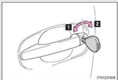
text_image
1 2 ITN12Y0031 Locks all doors
2 Unlocks all doors
Door lock switch

text_image
Diagram showing car seatbelt switch with labeled parts and directional arrows indicating movement or force1 Locks all doors
2 Unlocks all doors
Inside lock button

text_image
Diagram showing car interior components with numbered parts and a close-up view of the dashboard, labeled ITN12Y027.The front doors can be opened by pulling the inside handles even if the lock buttons are in the lock position.
Locking the front doors from the outside without a key
STEP 1 Move the inside lock button to the lock position.
STEP 2 Close the door while pulling the door handle.
▶ Vehicles with smart entry & start system
The door cannot be locked if the "ENGINE START STOP" switch is in ACCESSORY or IGNITION ON mode, or the electronic key is left inside the vehicle.
Depending on the position of the electronic key, the key may not be detected correctly and the door may be locked.
▶ Vehicles without smart entry & start system
The door cannot be locked if the key is in the engine switch.
Rear door child-protector lock
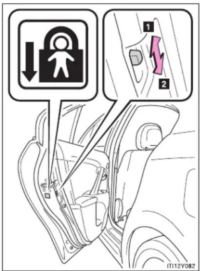
text_image
Diagram showing car door lock and safety instructions with labeled arrows and a highlighted sectionThe door cannot be opened from inside the vehicle when the locks are set.
1 Unlock
2 Lock
These locks can be set to prevent children from opening the rear doors. Push down the rear door switches to lock the rear doors.
Automatic door locking and unlocking systems
The following functions are available.
| Type Function | |
| Auto locking function | All doors are locked when the vehicle speed is approximately 20 km/h (12 mph) or higher*1 |
| Shifting the shift lever out of “P” locks all doors*2 | |
| Auto unlocking function | Shifting the shift lever to “P” unlocks all doors*2 |
| ▸ Vehicles with smart entry & start systemAll doors are unlocked when the driver’s door is opened within 45 seconds after turning the “ENGINE START STOP” switch OFF*1▸ Vehicles without smart entry & start systemAll doors are unlocked when the driver’s door is opened within 45 seconds after turning the engine switch to the “LOCK” position*1 |
*1: Default setting
*2: Vehicles with a Multidrive or automatic transmission
Setting and canceling the function (vehicles without a "touch screen")
Perform the operations of each function within 10 seconds.
- To set that all doors are locked when the vehicle speed is approximately 20 km/h (12 mph) or higher
STEP 1 Vehicles with smart entry & start system: Close all doors and turn the "ENGINE START STOP" switch to IGNITION ON mode.
Vehicles without smart entry & start system: Close all doors and turn the engine switch to "ON" position.
STEP 2 Shift the shift lever to "N".

text_image
STEP 3 ITN12Y060Press and hold the door lock switch for about 5 seconds.
STEP 4 Release the switch.
When the setting is complete, all doors are locked and then unlocked.
To cancel this function, use the same procedure as above (STEP 1 STEP 4).
1-2. Opening, closing and locking the doors
● To set that shifting the shift lever out of "P" locks all doors
STEP 1 Vehicles with smart entry & start system: Close all doors and turn the "ENGINE START STOP" switch to IGNITION ON mode.
Vehicles without smart entry & start system: Close all doors and turn the engine switch to "ON" position.
STEP 2 Shift the shift lever to "P".

text_image
STEP 3 ITN12Y060Press and hold the door lock switch for about 5 seconds.
STEP 4 Release the switch.
When the setting is complete, all doors are locked and then unlocked. To cancel this function, use the same procedure as above (STEP 1 STEP 4).
● To set that shifting the shift lever to "P" unlocks all doors
STEP 1 Vehicles with smart entry & start system: Close all doors and turn the "ENGINE START STOP" switch to IGNITION ON mode.
Vehicles without smart entry & start system: Close all doors and turn the engine switch to "ON" position.
STEP 2 Shift the shift lever to "P".

text_image
STEP 3 ITN12Y059Press and hold the door lock switch for about 5 seconds.
STEP 4 Release the switch.
When the setting is complete, all doors are locked and then unlocked. To cancel this function, use the same procedure as above (STEP 1 STEP 4).
1-2. Opening, closing and locking the doors
- To set that driver's door linked unlocks all doors
STEP 1 Vehicles with smart entry & start system: Close all doors and turn the "ENGINE START STOP" switch to IGNITION ON mode.
Vehicles without smart entry & start system: Close all doors and turn the engine switch to "ON" position.
STEP 2 Shift the shift lever to "N".
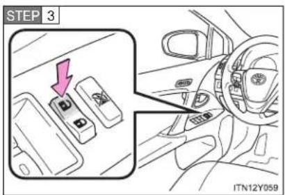
text_image
STEP 3 ITN12Y059Press and hold the door lock switch for about 5 seconds.
STEP 4 Release the switch.
When the setting is complete, all doors are locked and then unlocked. To cancel this function, use the same procedure as above (STEP 1 STEP 4).
Setting and canceling the function (vehicles with a "touch screen")
Customization can also be done by "touch screen". (Please refer to the "touch screen" Owner's Manual".)
■ Impact detection door lock release system
In the event that the vehicle is subject to a strong impact, all the doors are unlocked. Depending on the force of the impact or the type of accident, however, the system may not operate.
CAUTION
■ To prevent an accident
Observe the following precautions while driving the vehicle. Failing to do so may result in a door opening and an occupant falling out, resulting in death or serious injury.
• Always use a seat belt.
- Ensure that all doors are properly closed.
- Do not pull the inside handle of the doors while driving.
The doors may be opened and the passengers are thrown out of the vehicle and it may result in death or serious injury.
Be especially careful for the front doors, as the doors may be opened even if the inside lock buttons are in locked position.
- Set the rear door child-protector locks when children are seated in the rear seat.
1-2. Opening, closing and locking the doors
Trunk (sedan)
The trunk can be opened using the trunk opener.
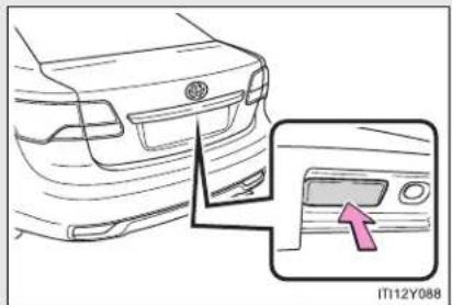
natural_image
Diagram of a car's rear bumper and side panel, showing a close-up of the front bumper with an arrow pointing to the side panel (no text or symbols present)Press the opener switch.
The trunk can be locked and unlocked using the smart entry & start system, wireless remote control or door lock switch.
■ Smart entry & start system (if equipped)
→P. 40
■ Wireless remote control
→P. 62
Door lock switch
→P. 79
Trunk light
The trunk light turns on when the trunk is opened.
Trunk handle
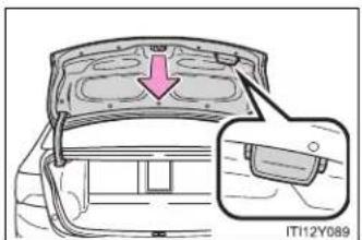
text_image
IT12Y089Use the trunk handle when closing the trunk.
Be careful not to pull the trunk lid sideways when closing the trunk with the handle.
If the trunk opener is inoperative or the battery is discharged
The trunk can opened from the inside. (→P. 700)
CAUTION
■ While driving
- Keep the trunk lid closed while driving.
If the trunk lid is left open, it may hit near-by objects while driving or luggage in the trunk may be unexpectedly thrown out, causing an accident.
In addition, exhaust gases may enter the vehicle, causing death or a serious health hazard. Make sure to close the trunk lid before driving.
Before driving the vehicle, make sure that the trunk lid is fully closed. If the trunk lid is not fully closed, it may open unexpectedly while driving, causing an accident. - Never let anyone sit in the trunk. In the event of sudden braking, sudden swerving or a collision, they are susceptible to death or serious injury.

CAUTION
■ When children are in the vehicle
Observe the following precautions.
Failure to do so may result in death or serious injury.
- Do not allow children to enter the trunk.
If a child is accidentally locked in the trunk, they could have heat exhaustion or suffocate. - Do not allow a child to open or close the trunk lid.
Doing so may cause the trunk lid operate unexpectedly, or cause the child's hands, head, or neck to be caught by the closing trunk lid.
■ Using the trunk
Observe the following precautions.
Failure to do so may cause parts of the body to be caught, resulting in serious injury.
- Remove any heavy loads, such as snow and ice, from the trunk lid before opening it. Failure to do so may cause the trunk lid to fall closed again after it is opened.
- When opening or closing the trunk lid, thoroughly check to make sure the surrounding area is safe.
- If anyone is in the vicinity, make sure they are safe and let them know that the trunk is about to open or close.
- Use caution when opening or closing the trunk lid in windy weather as it may move abruptly in strong wind.

CAUTION
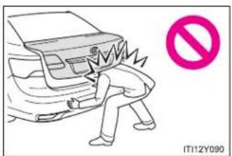
text_image
IT12Y090The trunk lid may fall if it is not opened fully. It is more difficult to open or close the trunk lid on an incline than on a level surface, so beware of the trunk lid unexpectedly opening or closing by itself. Make sure that the trunk lid is fully open and secure before using the trunk.

text_image
IT112Y091- When closing the trunk lid, take extra care to prevent your fingers etc. from being caught.
- When closing the trunk lid, make sure to press it lightly on its outer surface. If the trunk handle is used to fully close the trunk lid, it may result in hands or arms being caught.
- Do not attach any accessories other than genuine Toyota parts to the trunk lid. Such additional weight on the trunk lid may cause the lid to fall closed again after it is opened.
1-2. Opening, closing and locking the doors
Back door (wagon)
The back door can be opened using the back door opener.

natural_image
Line drawing of a car's rear bumper and side panel, with an inset showing a pink arrow pointing to the front panel (no text or symbols)Press the opener switch.
The back door can be locked and unlocked using the smart entry & start system, wireless remote control or door lock switch.
■ Smart entry & start system (if equipped)
→P. 40
■ Wireless remote control
→P. 62
Door lock switch
→P. 79
When closing the back door

text_image
IT112Y094aLower the back door using the back door handle, and make sure to push the back door down from the outside to close it.
Be careful not to pull the back door sideways when closing the back door with the handle.
Luggage compartment light
The luggage compartment light turns on when the back door is opened.
■ If the back door opener is inoperative or the battery is discharged
→P. 701
1-2. Opening, closing and locking the doors

CAUTION
■ While driving
- Keep the back door closed while driving. If the back door is left open, it may hit near-by objects while driving or luggage may be unexpectedly thrown out, causing an accident. In addition, exhaust gases may enter the vehicle, causing death or a serious health hazard. Make sure to close the back door before driving.
- Before driving the vehicle, make sure that the back door is fully closed. If the back door is not fully closed, it may open unexpectedly while driving, causing an accident. - Never let anyone sit in the luggage compartment. In the event of sudden braking, sudden swerving or a collision, they are susceptible to death or serious injury.

CAUTION
■ When children are in the vehicle
Observe the following precautions.
Failure to do so may result in death or serious injury.
- Do not leave children alone in the luggage compartment.
If a child is accidentally locked in the luggage compartment, they could have heat exhaustion. - Do not allow a child to open or close the back door.
Doing so may cause the back door to move unexpectedly, or cause the child's hands, head, or neck to be caught by the closing back door.
- Operating the back door
Observe the following precautions.
Failure to do so may cause parts of the body to be caught, resulting in death or serious injury.
- Remove any heavy loads, such as snow and ice, from the back door before opening it. Failure to do so may cause the back door to fall closed again after it is opened.
- When opening or closing the back door, thoroughly check to make sure the surrounding area is safe.
- If anyone is in the vicinity, make sure they are safe and let them know that the back door is about to open or close.
- Use caution when opening or closing the back door in windy weather as it may move abruptly in strong wind.
1-2. Opening, closing and locking the doors

CAUTION
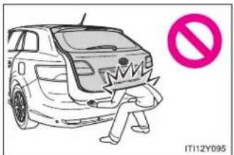
text_image
IT112Y095
text_image
IT12Y096The back door may fall if it is not opened fully. It is more difficult to open or close the back door on an incline than on a level surface, so beware of the back door unexpectedly opening or closing by itself. Make sure that the back door is fully open and secure before using the luggage compartment.
- When closing the back door, take extra care to prevent your fingers etc. from being caught.
- When closing the back door, make sure to press it lightly on its outer surface. If the back door handle is used to fully close the back door, it may result in hands or arms being caught.
- Do not pull on the back door damper stay to close the back door, and do not hang on the back door damper stay.
Doing so may cause hands to be caught or the back door damper stay to break, causing an accident.
If a bicycle carrier or similar heavy object is attached to the back door, it may fall closed again after being opened, causing someone's hands, head or neck to be caught and injured. When installing an accessory part to the back door, using a genuine Toyota part is recommended.

NOTICE
■ Back door damper stays
The back door is equipped with damper stays that hold the back door in place.
Observe the following precautions.
Failure to do so may cause damage to the back door damper stay, resulting in malfunction.

text_image
Damper stay IT112Y097Do not attach any foreign objects, such as stickers, plastic sheets, or adhesives to the damper stay rod.
- Do not touch the damper stay rod with gloves or other fabric items.
- Do not attach any accessories other than genuine Toyota parts to the back door.
- Do not place your hand on the damper stay or apply lateral forces to it.
1-3. Adjustable components (seats, mirrors, steering wheel) Front seats
▶ Power seat

text_image
1 2 3 4 5 ITN13Y0021 Seat position fore/aft control switch
2 Seatback angle control switch
3 Seat cushion (front) angle control switch
4 Vertical height control switch
5 Lumber support control switch (driver's side)
▶ Manual seat

text_image
1 2 3 4 ITN13Y0011 Seat position adjustment lever
2 Seatback angle adjustment lever
3 Vertical height adjustment lever (driver's side)
4 Lumbar support control switch (if equipped for driver's side)
Active head restraint
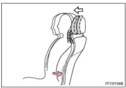
natural_image
Medical illustration of a hip joint with surgical hardware and force arrows (no text or symbols)When the occupant's back presses against the seatback during a rear-end collision, the head restraint moves slightly forward to help reduce the risk of whiplash on the seat occupant.
■ Active head restraint
Even small forces applied to the seatback may cause the head restraint to move. This does not indicate a problem.
CAUTION
Seat adjustment
- Be careful that the seat does not hit passengers or luggage.
- Do not recline the seat more than necessary when the vehicle is in motion to reduce the risk of sliding under the lap belt.
If the seat is too reclined, during an accident the lap belt may slide past the hips and apply restraint forces directly to the abdomen or your neck may contact the shoulder belt, increasing the risk of death or serious injury. - Manual seat: After adjusting the seat, make sure that the seat is locked in position.
1-3. Adjustable components (seats, mirrors, steering wheel) Rear seats
The seatbacks can be folded down.
Before folding down
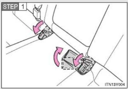
text_image
STEP 1 ITN13Y004Stow the seat belt buckles as shown.
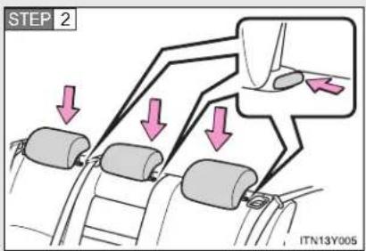
text_image
STEP 2 ITN13Y005Lower each of the head restraints while pushing the lock release button.
Sedan: When folding down the right hand seatback, also carry out the following procedure.
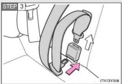
text_image
STEP 3 ITN13Y006Insert the tab into the hole on the center seat belt buckle to release tab (with hooked end), and allow the belt to retract.
1-3. Adjustable components (seats, mirrors, steering wheel)
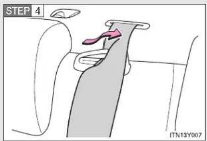
text_image
STEP 4 ITN13Y007Remove the seat belt from the seat belt guide.
■ Folding down the seatbacks
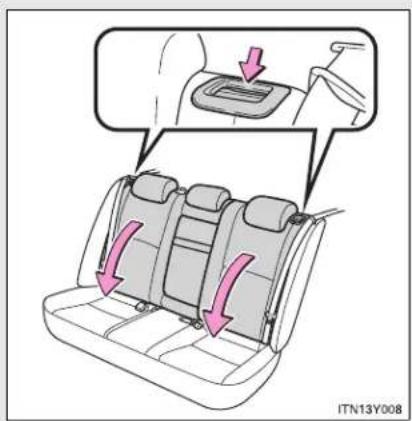
text_image
ITN13Y008Pull the lever to unlock the seatback and then fold the seatback down.
1-3. Adjustable components (seats, mirrors, steering wheel)
■ Returning the seatbacks (sedan)
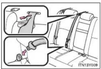
text_image
ITN13Y009Tilt the seatback up until it locks, making sure that you hold the seat belt to prevent it from getting caught between the seatback and the inner side of the vehicle.
Make sure the shoulder belt passes through the guide and that the seat belt is in position before folding down the seat when returning the seatback up.
CAUTION
■ When returning the seatbacks to the upright position
Observe the following precautions. Failure to do so may result in death or serious injury.
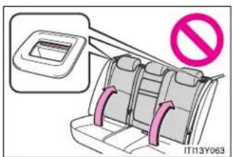
text_image
IT113Y063Make sure that the seatback is securely locked in position by lightly pushing it back and forth.
If the seatback is not securely locked, the red marking will be visible on the seatback lock release lever. Make sure that the red marking is not visible.
- Check that the seat belts are not twisted or caught in the seatback.
1-3. Adjustable components (seats, mirrors, steering wheel) Driving position memory system\*
Your preferred driving position (the position of the driver's seat and steering wheel) can be entered into the computer's memory and recalled with the touch of a button.
Two different driving positions can be entered into memory.
■ Entering a position to memory
STEP 1 Vehicles with smart entry & start system: Turn the "ENGINE START STOP" switch to IGNITION ON mode. Vehicles without smart entry & start system: Turn the engine switch to the "ON" position.
STEP 2 Adjust the driver's seat and steering wheel to the desired positions.
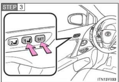
text_image
STEP 3 2 1 SET ITN13Y033Press the "SET" button, then within 3 seconds press button "1" or "2" until the signal beeps.
If the selected button has already been preset, the previously recorded position will be overwritten.
*: If equipped
1-3. Adjustable components (seats, mirrors, steering wheel)
■ Recalling the memorized position
STEP 1 Vehicles with smart entry & start system: Turn the "ENGINE START STOP" switch to IGNITION ON mode.
Vehicles without smart entry & start system: Turn the engine switch to the "ON" position.

text_image
STEP 2 2 1 SET ITN13Y034Press button "1" or "2" to recall the memorized position.
■ When entering or recalling the memory
Check that the shift lever is set in "P" (Multidrive or automatic transmission) or parking brake is set (manual transmission).
■ Retained accessory power
▶ Vehicles with smart entry & start system
- Memorized driver's seat position can be activated within 180 seconds after the driver's door is opened, even if the "ENGINE START STOP" switch turns OFF.
- Memorized driver's seat position can be recalled within 60 seconds after the driver's door is closed, even if the "ENGINE START STOP" switch is turned OFF.
▶ Vehicles without smart entry & start system
- Memorized driver's seat position can be activated within 180 seconds after the driver's door is opened, even if the engine switch turns to "LOCK" position.
- Memorized driver's seat position can be recalled within 60 seconds after the driver's door is closed, even if the engine switch is turned off.
■ To cancel seat position recall
Perform one of the following operations.
- Press the "SET" button
- Press button "1" or "2"
- Adjust the seat using the switches (only cancels seat position recall)

CAUTION
- Seat adjustment caution
Take care during seat adjustment that the seat does not strike the rear passenger or squeeze your body against the steering wheel.
1-3. Adjustable components (seats, mirrors, steering wheel) Head restraints
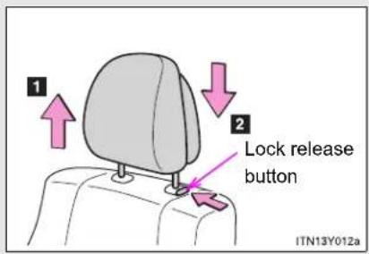
text_image
1 2 Lock release button ITN13Y012aVertical adjustment
1 Up
Pull the head restraints up.
2 Down
Press and hold the lock release button when lowering the head restraint.
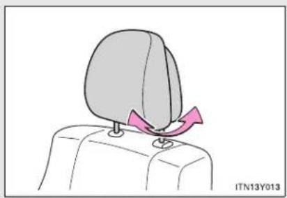
natural_image
Illustration of a person's head with a pink triangular object on the shoulder, no text or symbols presentAngle adjustment (if equipped for front seats)
■ Adjusting the height of the head restraints

natural_image
Side profile illustration of a human head and neck with a shaded anatomical region, no text or symbols presentMake sure that the head restraints are adjusted so that the center of the head restraint is closest to the top of your ears.
■ Adjusting the rear seat head restraint
Always raise the head restraint one level from the stowed position when using.
■ Removing and installing the front seat head restraints
For removal and installation, ask any authorized Toyota dealer or repairer, or another duly qualified and equipped professional.
■ Removing the rear seat head restraints
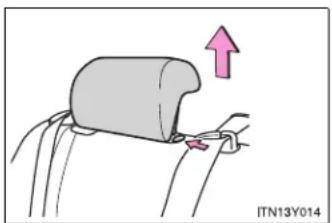
natural_image
Diagram of a car seatbelt being adjusted with an arrow indicating upward motion (no text or symbols)Pull the head restraint up while pressing the lock release button.
■ Installing the rear seat head restraints
STEP 1 Align the head restraint with the installation holes.
STEP 2 Push down the head restraint to the lock position.
CAUTION
■ Head restraint precautions
Observe the following precautions regarding the head restraints. Failure to do so may result in death or serious injury.
- Use the head restraints designed for each respective seat.
- Adjust the head restraints to the correct position at all times.
- After adjusting the head restraints, push down on them and make sure they are locked in position.
- Do not drive with the head restraints removed.
1-3. Adjustable components (seats, mirrors, steering wheel) Seat belts
Make sure that all occupants are wearing their seat belts before driving the vehicle.
■ Correct use of the seat belts
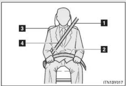
text_image
1 2 3 4 ITN13Y0171 Extend the shoulder belt so that it comes fully over the shoulder, but does not come into contact with the neck or slide off the shoulder.
2 Position the lap belt as low as possible over the hips.
3 Adjust the position of the seatback. Sit up straight and well back in the seat.
4 Do not twist the seat belt.
■ Fastening and releasing the seat belt

text_image
1 2 Release button ITN13Y0181 Fastening the belt
Push the tab into the buckle until a clicking sound is heard.
2 Releasing the belt
Press the release button.
■ Adjusting the height of the belt (front seats)
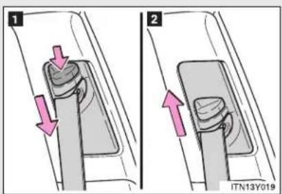
text_image
1 2 ITN13Y0191 Down
2 Up
Move the height adjuster up and down as needed until you hear a click.
Seat belt pretensioners (front seats)

natural_image
Interior view of a car showing driver, steering wheel, and dashboard (no text or symbols visible)The pretensioner helps the seat belt to quickly restrain the occupant by retracting the seat belt when the vehicle is subjected to certain types of severe frontal collision.
The pretensioner may not activate in the event of a minor frontal impact, a side impact or a rear impact.
Pre-crash seat belts (front seats of vehicles with pre-crash safety system)
If the pre-crash sensor detects that a collision is unavoidable, the pre-crash safety system will retract the seat belt, thus enhancing the effectiveness of the seat belt pretensioner in a crash.
The same will happen if the driver makes an emergency braking or loses control of the vehicle. (→P. 333)
Emergency locking retractor (ELR)
The retractor will lock the belt during a sudden stop or on impact. It may also lock if you lean forward too quickly. A slow, easy motion will allow the belt to extend so that you can move around fully.
■ Pregnant women

natural_image
Two illustrations of a person seated in car seats, one using a seatbelt and the other with a diagonal brace (no text or symbols)Obtain medical advice and wear the seat belt in the proper way. (→P. 108)
Women who are pregnant should position the lap belt as low as possible over the hips in the same manner as other occupants. Extend the shoulder belt completely over the shoulder and position the belt across the chest. Avoid belt contact over the rounding of the abdominal area.
If the seat belt is not worn properly, not only a pregnant woman, but also the fetus could suffer death or serious injury as a result of sudden braking or a collision.
1-3. Adjustable components (seats, mirrors, steering wheel)
■ People suffering illness
Obtain medical advice and wear the seat belt in the proper way.
■ Child seat belt usage
The seat belts of your vehicle were principally designed for persons of adult size.
- Use a child restraint system appropriate for the child, until the child becomes large enough to properly wear the vehicle's seat belt. (→P. 168)
- When the child becomes large enough to properly wear the vehicle's seat belt, follow the instructions on P. 108 regarding seat belt usage.
■ Replacing the belt after the pretensioner has been activated
If the vehicle is involved in multiple collisions, the pretensioner will activate for the first collision, but will not activate for the second or subsequent collisions.
- Seat belt regulations
If seat belt regulations exist in the country where you reside, contact any authorized Toyota dealer or repairer, or another duly qualified and equipped professional, for seat belt replacement or installation.

CAUTION
Observe the following precautions to reduce the risk of injury in the event of sudden braking, sudden swerving or an accident.
Failing to do so may cause death or serious injury.
■ Wearing a seat belt
- Ensure that all passengers wear a seat belt.
• Always wear a seat belt properly. - Each seat belt should be used by one person only. Do not use a seat belt for more than one person at once, including children.
Toyota recommends that children be seated in the rear seat and always use a seat belt and/or an appropriate child restraint system. - Do not recline the seat any more than necessary to achieve a proper seating position. The seat belt is most effective when the occupants are sitting up straight and well back in the seats.
- Do not wear the shoulder belt under your arm.
● Always wear your seat belt low and snug across your hips.
■ When children are in the vehicle
Do not allow children to play with the seat belt. If the seat belt becomes twisted around a child's neck, it may lead to choking or other serious injuries that could result in death.
If this occurs and the buckle cannot be unfastened, scissors should be used to cut the belt.

CAUTION
- Seat belt pretensioners
- Do not place anything, such as a cushion, on the front passenger's seat. Doing so will disperse the passenger's weight, which prevents the sensor from detecting the passenger's weight properly. As a result, the seat belt pretensioner for the front passenger's seat may not activate in the event of a collision.
- If the pretensioner has activated, the SRS warning light will come on. In that case, the seat belt cannot be used again and must be replaced at any authorized Toyota dealer or repairer, or another duly qualified and equipped professional.
- Seat belt damage and wear
- Do not damage the seat belts by allowing the belt, plate, or buckle to be jammed in the door.
- Inspect the seat belt system periodically. Check for cuts, fraying, and loose parts. Do not use a damaged seat belt until it is replaced. Damaged seat belt cannot protect an occupant from death or serious injury.
- Ensure that the belt and tab are locked and the belt is not twisted. If the seat belt does not function correctly, immediately contact any authorized Toyota dealer or repairer, or another duly qualified and equipped professional.
- Replace the seat assembly, including the belts, if your vehicle has been involved in a serious accident, even if there is no obvious damage.
- Do not attempt to install, remove, modify, disassemble or dispose of the seat belts. Have any necessary repairs carried out by any authorized Toyota dealer or repairer, or another duly qualified and equipped professional. Inappropriate handling of the pretensioner may prevent it from operating properly resulting in death or serious injury.

CAUTION
- Seat belt damage and wear
For sedan:
● Always make sure the shoulder belt passes through the guide when using the seat belt. Failure to properly position the belt may reduce the amount of protection in an accident and could lead to serious injuries in a collision or sudden stop.
● Always make sure that the seat belt is not twisted, does not get caught in the guide or the seatback and is arranged in the proper position.
■ When using the rear center seat belt (sedan)
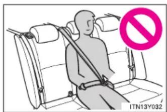
text_image
ITN13Y032Do not use the rear center seat belt with either buckle released. Fastening only one of the buckles may result in death or serious injury in case of sudden braking or a collision.
■ Precaution for pre-crash seat belts
Do not rely on the pre-crash safety to avoid accidents. Always pay attention to the surrounding conditions, and drive safely and responsibly.
1-3. Adjustable components (seats, mirrors, steering wheel) Steering wheel
The steering wheel can be adjusted to a comfortable position.
▶ Power tilt & telescopic steering wheel

text_image
1 2 3 4 ITN13Y0371 Up
2 Down
3 Toward the driver
4 Away from the driver
▶ Manual tilt & telescopic steering wheel

text_image
STEP 1 ITN13Y045Hold the steering wheel and press the lever down.
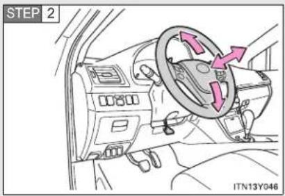
text_image
STEP 2 ITN13Y046Adjust to the ideal position by moving the steering wheel horizontally and vertically.
After adjustment, pull the lever up to secure the steering wheel.
Auto tilt away (vehicles with power tilt & telescopic steering wheel)

text_image
ENGINE START STOP IT13Y072When the "ENGINE START STOP" switch is turned OFF, the steering wheel returns to its stowed position by moving up and away to enable easier driver entry and exit.
Switching to ACCESSORY or IGNITION ON mode will return the steering wheel to the original position.
The power tilt & telescopic steering wheel can be operated when
The "ENGINE START STOP" switch is in ACCESSORY or IGNITION ON mode.
■ Automatic adjustment of the steering position (if equipped)
A desired steering position can be entered to memory and recalled automatically by the driving position memory. (→P. 103)
1-3. Adjustable components (seats, mirrors, steering wheel)

CAUTION
■ While driving
Do not adjust the steering wheel.
Doing so may cause the driver to mishandle the vehicle and cause an accident, resulting in death or serious injury.
■ After adjusting the steering wheel (vehicles with manual tilt & telescopic steering wheel)
Make sure that the steering wheel is securely locked by trying to move the steering wheel up and down.
Otherwise, the steering wheel may move suddenly, possibly causing an accident and resulting in death or serious injury.
1-3. Adjustable components (seats, mirrors, steering wheel) Inside rear view mirror
Glare from the headlights of vehicles behind can be reduced by using the following functions.
▶ Auto anti-glare inside rear view mirror
In auto mode, sensors are used to detect the headlights of vehicles behind and automatically reduce the reflected light.
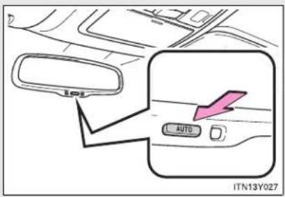
text_image
101 AUTO ITN13Y027Turns auto mode on/off
The indicator comes on when auto mode is turned on.
Vehicles with smart entry & start system:
The mirror will revert to the auto mode each time the "ENGINE START STOP" switch is turned to IGNITION ON mode.
Vehicles without smart entry & start system:
The mirror will revert to the auto mode each time the engine switch is turned to the "ON" position.
1-3. Adjustable components (seats, mirrors, steering wheel)
▶ Manual anti-glare inside rear view mirror

text_image
1 2 ITN13Y026a1 Normal position
2 Anti-glare position
Adjusting the height of rear view mirror (vehicles with auto anti-glare inside rear view mirror)

natural_image
Diagram showing a mechanical component with a dashed outline and a pink double-headed arrow indicating vertical displacement (no text or symbols)Adjust the height of the rear view mirror by moving it up and down.
■ To prevent sensor error (vehicles with auto anti-glare inside rear view mirror)
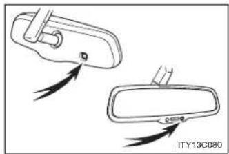
natural_image
Diagram showing two views of a car door, one with a handle and arrow indicator, the other with a handle and arrow indicator (no text or symbols)To ensure that the sensors operate properly, do not touch or cover them.

CAUTION
While driving
Do not adjust the position of the mirror.
Doing so may lead to mishandling of the vehicle and an accident, resulting in death or serious injury.
1-3. Adjustable components (seats, mirrors, steering wheel) Outside rear view mirrors
Mirror angle can be adjusted using the switch.

text_image
STEP 1 L R 1 2 ITN13Y040Select a mirror to adjust.
1 Left
2 Right
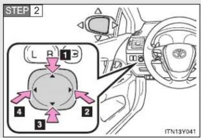
text_image
STEP 2 L R 13 4 2 3 ITN13Y041Adjust the mirror.
1 Up
2 Right
3 Down
4 Left
Folding back the mirrors
▶ Power type (if equipped)

text_image
L R ITN13Y042Press the switch.
Pressing again will extend the mirror.
▶ Manual type

natural_image
Illustration of a gray ergonomic seat with a pink curved arrow indicating rotation (no text or symbols)Push backward to fold the mirrors.
The outside rear view mirrors can be operated when
▶ Vehicles with smart entry & start system
The "ENGINE START STOP" switch is in ACCESSORY or IGNITION ON mode.
▶ Vehicles without smart entry & start system
The engine switch is in the "ACC" or "ON" position.
■ When the mirrors are fogged up
The outside rear view mirrors can be cleared using the mirror heaters. Turn on the rear window defogger to turn on the outside rear view mirror heaters. (→P. 381)
1-3. Adjustable components (seats, mirrors, steering wheel)

CAUTION
While driving
Observe the following precautions.
Failing to do so may result in loss of control of the vehicle and cause an accident, resulting in death or serious injury.
Do not adjust the mirrors.
Do not drive with the mirrors folded back.
- Both the driver and passenger side mirrors must be extended and properly adjusted before driving.
When a mirror is moving
To avoid injury and mirror malfunction, be careful not to get your hand caught by the moving mirror.
■ When the mirror defoggers are operating
Do not touch the rear view mirror surfaces, as they can become very hot and burn you.

NOTICE
If ice should jam the mirror
Do not operate the control or scrape the mirror face. Use a spray de-icer to free the mirror.
1-4. Opening and closing the windows
Power windows
The power windows can be opened and closed using the following switches.
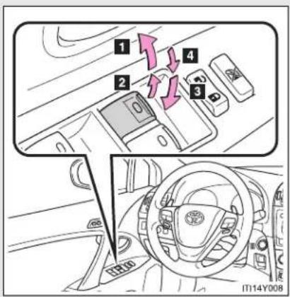
text_image
1 2 3 4 IT14Y0081 One-touch closing (if equipped)*
2 Closing
3 One-touch opening (if equipped)*
4 Opening
*: Pressing the switch in the opposite direction will stop window travel partway.
Lock switch

text_image
ITN14Y004Press the switch down to lock passenger window switches.
Use this switch to prevent children from accidentally opening or closing a passenger window.
1-4. Opening and closing the windows
■ The power windows can be operated when
▶ Vehicles with smart entry & start system
The "ENGINE START STOP" switch is in IGNITION ON mode.
▶ Vehicles without smart entry & start system
The engine switch is in the "ON" position.
■ Retained accessory power
▶ Vehicles with smart entry & start system
The power windows can be operated for approximately 45 seconds even after the "ENGINE START STOP" switch is turned to ACCESSORY mode or turned OFF. They cannot, however, be operated once either front door is opened.
▶ Vehicles without smart entry & start system
The power windows can be operated for approximately 45 seconds even after the engine switch is turned to the "ACC" or "LOCK" position. They cannot, however, be operated once either front door is opened.
Jam protection function
If an object becomes caught between the window and the window frame, window travel is stopped and the window is opened slightly.
■ When the power window does not close normally
If the jam protection function is operating abnormally and a window cannot be closed, perform the following operations using the power window switch on the relevant door.
- After stopping the vehicle, the window can be closed by holding the power window switch in the one-touch closing position while the "ENGINE START STOP" switch is turned to IGNITION ON mode (vehicles with smart entry & start system) or the engine switch is turned to the "ON" position (vehicles without smart entry & start system).
- If the window still cannot be closed even by carrying out the operation explained above, initialize the function by performing the following procedure.
STEP 1 Hold the power window switch in the one-touch closing position. Continue holding the switch for a further 6 seconds after the window has closed.
STEP 2 Hold the power window switch in the one-touch opening position. Continue holding the switch for a further 2 seconds after the window has opened completely.
STEP 3 Hold the power window switch in the one-touch closing position once again. Continue holding the switch for a further 2 seconds after the window has closed.
If you release the switch while the window is moving, start again from the beginning. If the window continues to close but then re-open slightly even after performing the above procedure correctly, have the vehicle inspected by any authorized Toyota dealer or repairer, or another duly qualified and equipped professional.
1-4. Opening and closing the windows

CAUTION
■ When closing the windows
Observe the following precautions.
Failing to do so may result in death or serious injury.
- Check to make sure that all passengers do not have any part of their body in a position where it could be caught when a window is being operated.
- Do not allow children to operate the power windows.
Closing a power window on someone can cause serious injury, and in some instances, even death.
Jam protection function
- Never try jamming any part of your body to activate the jam protection function intentionally.
- The jam protection function may not work if something gets caught just before the window fully closes.
1-5. Refueling
Opening the fuel tank cap
Perform the following steps to open the fuel tank cap.
■ Before refueling the vehicle
▶ Vehicles with smart entry & start system
Turn the "ENGINE START STOP" switch OFF and ensure that all the doors and windows are closed.
▶ Vehicles without smart entry & start system
Turn the engine switch to the "LOCK" position and ensure that all the doors and windows are closed.
■ Opening the fuel tank cap

text_image
STEP 1 ITN15Y001Press the fuel filler door opener switch.
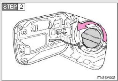
text_image
STEP 2 ITN15Y002Turn the fuel tank cap slowly to open.
1-5. Refueling
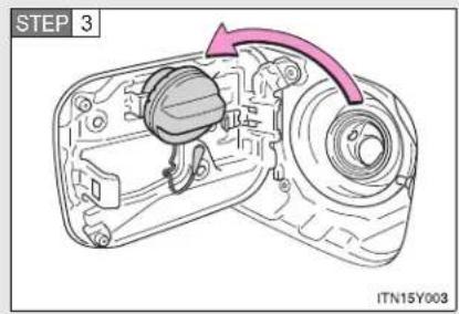
text_image
STEP 3 ITN15Y003Hang the fuel tank cap on the back of the fuel filler door.
Closing the fuel tank cap

natural_image
Technical line drawing of a camera body with a highlighted lens and cable (no text or symbols)When replacing the fuel tank cap, turn it until a clicking sound is heard.
After releasing your hand, the cap will turn slightly to the opposite direction.
Fuel types
▶ Gasoline engine
EU area:
Unleaded gasoline conforming to European standard EN228, Research Octane Number of 95 or higher
Except EU area:
Unleaded gasoline, Research Octane Number of 95 or higher
▶ Diesel engine
| Engine/catalytic converter Type | |
| 1AD-FTV engine without DPF catalytic converter | EU area:Diesel fuel conforming to European standard EN590Except EU area:Diesel fuel that contains 500 ppm or less of sulfur and has a cetane number of 48 or higher |
| 1AD-FTV engine with DPF catalytic converter, 2AD-FTV and 2AD-FHV engines | EU area:Diesel fuel conforming to European standard EN590Except EU area:Diesel fuel that contains 50 ppm or less of sulfur and has a cetane number of 48 or higher |
1-5. Refueling
■ Use of ethanol blended gasoline in a gasoline engine
Toyota allows the use of ethanol blended gasoline where the ethanol content is up to 10%. Make sure that the ethanol blended gasoline to be used has a Research Octane Number that follows the above.
Fuel tank capacity
Approximately 60 L (15.9 gal., 13.2 Imp.gal.)
■ When the fuel filler door opener switch is inoperable
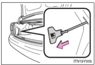
text_image
ITN15Y005Pull the lever slowly rearward (not sideways) as shown in the illustration.
The lever can be used to open the fuel filler door if the fuel filler door cannot be opened using the inside switch because the battery discharged or for any other reason.

CAUTION
■ Refueling the vehicle
Observe the following precautions while refueling the vehicle. Failure to do so may result in death or serious injury.
- Touch the vehicle or some other metal surface to discharge any static electricity.
Sparks resulting from discharging static electricity may cause the fuel vapors to ignite.
● Always hold the grips on the fuel tank cap and turn it slowly to remove it. A whooshing sound may be heard when the fuel tank cap is loosened. Wait until the sound cannot be heard before fully removing the cap.
In hot weather, pressurized fuel may spray out of the filler neck and cause injury.
- Do not allow anyone that has not discharged static electricity from their bodies to come close to an open fuel tank.
- Do not inhale vaporized fuel.
Fuel contains substances that are harmful if inhaled.
- Do not smoke while refueling the vehicle.
Doing so may cause the fuel to ignite and cause a fire.
- Do not return to the vehicle or touch any person or object that is statically charged.
This may cause static electricity to build up, resulting in a possible ignition hazard.
1-5. Refueling

CAUTION
■ When replacing the fuel tank cap
Do not use anything but a genuine Toyota fuel tank cap designed for your vehicle. Failure to do so may cause a fire or other incident which may result in death or serious injury.

NOTICE
Refueling
Do not spill fuel during refueling.
Failure to do so may damage the vehicle, such as causing the exhaust systems to operate abnormally or damaging fuel system components or the vehicle's painted surface.
■ Fuel filler door emergency release lever
- Do not pull the lever strongly.
- Do not use the lever except in an emergency.
1-6. Theft deterrent system
Engine immobilizer system
The vehicle's keys have built-in transponder chips that prevent the engine from starting if the key has not been previously registered in the vehicle's on-board computer.
Never leave the keys inside the vehicle when you leave the vehicle.
▶ Vehicles with smart entry & start system

text_image
SECURITY F IT116Y033The indicator light flashes after the "ENGINE START STOP" switch has been turned OFF to indicate that the system is operating.
The indicator light stops flashing after the "ENGINE START STOP" switch has been turned to ACCESSORY or IGNITION ON mode to indicate that the system has been canceled.
1-6. Theft deterrent system
▶ Vehicles without smart entry & start system

text_image
SECURITY F IT16Y033The indicator light flashes after the key has been removed from the engine switch to indicate that the system is operating.
The indicator light stops flashing after the registered key has been inserted into the engine switch to indicate that the system has been canceled.
System maintenance
The vehicle has a maintenance-free type engine immobilizer system.
■ Conditions that may cause the system to malfunction
- If the key is in contact with a metallic object
- If the key is in close proximity to or touching a key to the security system (key with a built-in transponder chip) of another vehicle
■ Engine immobilizer certification (vehicles with smart entry & start system)
Hereby, Toyota Motor Corporation, declares that this TMIMB-1 is in compliance with the essential requirements and other relevant provisions of Directive 1999/5/EC.
TOYOTA TOYOTA MOTOR CORPORATION
- TOYOTA-CHO, TOYOTA, ACH, 471-8571(Head Office) or 471-8572(Research & Development Group) JAPAN TEL: (0565)28-2121
R&TTE Declaration of Conformity
We,
Manufacturer's Name: TOYOTA MOTOR CORPORATION Manufacturer's Address: 1, Toyota-cho, Toyota, Aichi, 471-8572 Japan
hereby declare under our sole responsibility that the product:
Product Name: Immobilizer Product Model: TMIMB-1
to which this declaration relates is in conformity with the essential requirements and other relevant requirements of the R&TTE Directive (1999/5/EC). The product is compliant with the following standards and/or other normative documents:
- Health & safety requirements: EN60950-1:2001
- EMC requirements: EN301 489-1 V1.4.1 & EN301 489-3 V1.4.1
- Effective use of radio spectrum: EN300 330-2 V1.1.1
Supplementary information:
| * CE mark | CE |
| * Member states intended for use | EU and EFTA |
Date:
Signature:
September 17, 2004

1-6. Theft deterrent system
| Hereby, Toyota Motor Corporation, declares that this TMIMB-1 is in compliance with the essential requirements and other relevant provisions of Directive 1999/5/EC. |
| Toyota Motor Corporation vakuuttaa täten että TMIMB-1 typpinen laite on direktiivin 1999/5/EY oleellisten vaatimusten ja sitä koskevien direktiivin muiden ehtojen mukainen. |
| Hierbij verklaart Toyota Motor Corporation dat het toestel TMIMB-1 in overeenstemming is met de essentiële eisen en de andere relevante bepalingen van richtlijn 1999/5/EG. |
| Par la présente Toyota Motor Corporation déclare que l'appareil TMIMB-1 est conforme aux exigences essentielles et aux autres dispositions pertinentes de la directive 1999/5/CE. |
| Härmed intygar Toyota Motor Corporation att denna TMIMB-1 står I överensstämmelse med de väsentliga egenskapskrav och övriga relevanta bestämmelser som framgår av direktiv 1999/5/EG. |
| Undertegnede Toyota Motor Corporation erklærer herved, at følgende udstyr TMIMB-1 overholder de väsentlige krav og øvrige relevante krav i direktiv 1999/5/EF. |
| Hiermit erklärt Toyota Motor Corporation, dass sich das Gerät TMIMB-1 in Übereinstimmung mit den grundlegenden Anforderungen und den übrigen einschlägigen Bestimmungen der Richtlinie 1999/5/EG befindet. |
| ME THN ΠΑΡΟΥΣΑ Toyota Motor Corporation ΔΗΛΩΝΕΙ ΟΤΙ TMIMB-1 ΣΥΜΜΟΡΦΩΝΕΤΑΙ ΠΡΟΣ ΤΙΣ ΟΥΣΙΩΔΕΙΣ ΑΠΑΙΤΗΣΕΙΣ ΚΑΙ ΤΙΣ ΛΟΙΠΕΣ ΣΧΕΤΙΚΕΣ ΔΙΑΤΑΞΕΙΣ ΤΗΣ ΟΔΗΓΙΑΣ 1999/5/EK. |
| Con la presente Toyota Motor Corporation dichiara che questo TMIMB-1 è conforme ai requisiti essenziali ed alle altre disposizioni pertinenti stabilite dalla direttiva 1999/5/CE. |
| Por medio de la presente Toyota Motor Corporation declara que el TMIMB-1 cumple con los requisitos esenciales y cualesquiera otras disposiciones aplicables o exigibles de la Directiva 1999/5/CE. |
| Toyota Motor Corporation declara que este TMIMB-1 está conforme com os requisitos essenciais e outras disposições da Directiva 1999/5/CE. |
| Hawnhekk, Toyota Motor Corporation, jiddikjara li dan TMIMB-1 jikkonforma mal-ħtiġijiet essenzjali u ma provvedimenti oħrajn relevanti li hemm fid-Dirrettiva 1999/5/EC. |
| Käesolevaga kinnitab Toyota Motor Corporation seadme TMIMB-1 vastavust direktiivi 1999/5/EÜ põhinõuetele ja nimetatud direktiivist tulenevatele teistele asjakohastele sätetele. |
| Alulírott, Toyota Motor Corporation nyilatkozom, hogy a TMIMB-1 megfelel a vonatkozó alapvető követelményeknek és az 1999/5/EC irányelv egyéb előírásainak. |
| Toyota Motor Corporation týmto vyhlasuje, že TMIMB-1 splňa základné požiadavky a všetky príslušné ustanovenia Smernice 1999/5/ES. |
| Toyota Motor Corporation tímto prohlašuje, že tento TMIMB-1 je ve shodě se základními požadavky a dalšími příslušnými ustanoveními směrnice 1999/5/ES. |
| Toyota Motor Corporation izjavlja, da je ta TMIMB-1 v skladu z bistvenimi zahtevami in ostalimi relevantnimi določili direktive 1999/5/ES. |
| Šiuo Toyota Motor Corporation deklaruoja, kad šis TMIMB-1 atitinka esminius reikalavimus ir kitas 1999/5/EB Direktyvos nuostatas. |
| Ar šo Toyota Motor Corporation deklarě, ka TMIMB-1 atbilst Direktīvas 1999/5/EK būtiskajām prasībām un citiem ar to saistītajiem noteikumiem. |
| Niniejszym Toyota Motor Corporation oświadcza, že TMIMB-1 jest zgodny z zasadniczymi wymogami oraz pozostałymi stosownymi postanowieniami Dyrektywy 1999/5/EC. |
| Hér með lýsir Toyota Motor Corporation yfir pví að TMIMB-1 er i samræmi við grunnkröfur og aðrar kröfur, sem gerðar eru i tilskipun 1999/5/EC. |
| Toyota Motor Corporation erklærer herved at utstyret TMIMB-1 er i samsvar med de grunnleggende krav og øvrige relevante krav i direktiv 1999/5/EF. |
| Ovim, Toyota Motor Corporation, izjavljuje da ovaj TMIMB-1 je usklađen sa bitnim zahtjevima i drugim relevantnim odredbama Direktive 1999/5/EC. |
1-6. Theft deterrent system
■ Engine immobilizer certification (vehicles without smart entry & start system)
Hereby, TRCZ s.r.o., declares that this RI-37BTY is in compliance with the essential requirements and other relevant provisions of Directive 1999/5/EC.
TRCZ
R&TTE Declaration of Conformity
We,
Manufacturer's Name: TRCZ s.r.o.
Manufacturer's Address: Prumyslova 1165, 410 02, Lovosice, Czech Republic
hereby declare under our sole responsibility that the product:
Product Name: Immobilizer
Product Model: RI-37BTY
to which this declaration relates is in conformity with the essential requirements and other relevant requirements of the R&TTE Directive (1999/5/EC). The product is compliant with the following standards and/or other normative documents:
Safety: EN60950-1
EMC: EN301 489-1 & -3
Spectrum: EN300 330-2
Supplementary information:
| * CE mark | CE |
| * Member states intended for use | EU and EFTA |
| * Member states with restrictive use | None |
Date:
Signature:
Position of the signatory:
6 September 2010
Plant manager
| TRCZ s.r.o. vakuuttaa täten että RI-37BTY typpinen laite on direktiivin 1999/5/EY oleellisten vaatimusten ja sitä koskevien direktiivin muiden ehtojen mukainen. |
| Hierbij verklaart TRCZ s.r.o. dat het toestel RI-37BTY in overeenstemming is met de essentiële eisen en de andere relevante bepalingen van richtlijn 1999/5/EG. |
| Par la présente TRCZ s.r.o. déclare que l'appareil RI-37BTY est conforme aux exigences essentielles et aux autres dispositions pertinentes de la directive 1999/5/CE. |
| Härmed intygar TRCZ s.r.o. att denna RI-37BTY står l överensstämmelse med de väsentliga egenskapskrav och övriga relevanta bestämmelser som framgår av direktiv 1999/5/EG. |
| Undertegnede TRCZ s.r.o. erklærer herved, at følgende udstyr RI-37BTY overholder de væsentlige krav og øvrige relevante krav i direktiv 1999/5/EF. |
| Hiermit erklärt TRCZ s.r.o., dass sich das Gerät RI-37BTY in Übereinstimmung mit den grundlegenden Anforderungen und den übrigen einschlägigen Bestimmungen der Richtlinie 1999/5/EG befindet. |
| ME THN ΠΑΡΟΥΣΑ TRCZ s.r.o. ΔΗΛΩΝΕΙ ΟΤΙ RI-37BTY ΣΥΜΜΟΡΦΩΝΕΤΑΙ ΠΡΟΣ ΤΙΣ ΟΥΣΙΩΔΕΙΣ ΑΠΑΙΤΗΣΕΙΣ ΚΑΙ ΤΙΣ ΛΟΙΠΕΣ ΣΧΕΤΙΚΕΣ ΔΙΑΤΑΞΕΙΣ ΤΗΣ ΟΔΗΓΙΑΣ 1999/5/EK. |
| Con la presente TRCZ s.r.o. dichiara che questo RI-37BTY è conforme ai requisiti essenziali ed alle altre disposizioni pertinenti stabilite dalla direttiva 1999/5/CE. |
| Por medio de la presente TRCZ s.r.o. declara que el RI-37BTY cumple con los requisitos esenciales y cualesquiera otras disposiciones aplicables o exigibles de la Directiva 1999/5/CE. |
| TRCZ s.r.o. declara que este RI-37BTY está conforme com os requisitos essenciais e outras disposições da Directiva 1999/5/CE. |
| Hawnhekk, TRCZ s.r.o., jiddikjara li dan RI-37BTY jikkonforma mal-ħtiġijiet essenzjali u ma provvedimenti oħrajn relevanti li hemm fid-Dirrettiva 1999/5/EC. |
| Käesolevaga kinnitab TRCZ s.r.o. seadme RI-37BTY vastavust direktiivi 1999/5/EÜ põhinõuetele ja nimetatud direktiivist tulenevatele teistele asjakohastele sätetele. |
1-6. Theft deterrent system
| Alulírott, TRCZ s.r.o. nyilatkozom, hogy a RI-37BTY megfelel a vonatkozó alapvető követelményeknek és az 1999/5/EC irányelv egyéb előírásainak. |
| TRCZ s.r.o. týmto vyhlasuje, že RI-37BTY spíňa základné požiadavky a všetky príslušné ustanovenia Smernice 1999/5/ES. |
| TRCZ s.r.o. tímto prohlašuje, že tento RI-37BTY je ve shodě se základními požadavky a dalšími příslušnými ustanoveními směrnice 1999/5/ES. |
| TRCZ s.r.o. izjavlja, da je ta RI-37BTY v skladu z bistvenimi zahtevami in ostalími relevantními določili direktive 1999/5/ES. |
| Šiuo TRCZ s.r.o. deklaruoja, kad šis RI-37BTY atitinka esminius reikalavimus ir kitas 1999/5/EB Direktyvos nuostatas. |
| Ar šo TRCZ s.r.o. deklarě, ka RI-37BTY atbilst Direktīvas 1999/5/EK būtiskajām prasībām un citiem ar to saistītajiem noteikumiem. |
| Niniejszym TRCZ s.r.o. oświadcza, že RI-37BTY jest zgodny z zasadniczymi wymogami oraz pozostałymi stosownymi postanowieniami Dyrektywy 1999/5/EC. |
| Hér með lýsir TRCZ s.r.o. yfír því að RI-37BTY er í samræmi við grunnkröfur og aðrar kröfur, sem gerðar eru í tilskipun 1999/5/EC. |
| TRCZ s.r.o. erklærer herved at utsyret RI-37BTY er i samsvar med de grunnleggende krav og øvrige relevante krav i direktiv 1999/5/EF. |
| Ovim, TRCZ s.r.o. izjavljuje da ovaj RI-37BTY je usklađen sa bitnim zahtjevima i drugim relevantním odredbama Direktive 1999/5/EC. |

NOTICE
■ To ensure the system operates correctly
Do not modify or remove the system. If modified or removed, the proper operation of the system cannot be guaranteed.
1-6. Theft deterrent system
Double locking system\*
Unauthorized access to the vehicle is prevented by disabling the door unlocking function from both the interior and exterior of the vehicle.
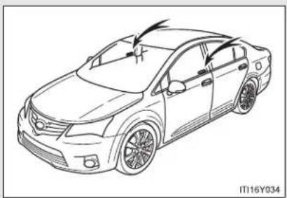
natural_image
Line drawing of a sedan car with arrows indicating motion or change, no text or symbols presentVehicles employing this system have labels on the window glass of both front doors.
Setting the system
▶ Vehicles with smart entry & start system
Turn the "ENGINE START STOP" switch OFF, have all the passengers exit the vehicle and ensure that all the doors are closed.
Using the smart entry & start system:
Touch the sensor area on the outside door handle twice within 5 seconds.
Using the wireless remote control:
Press the 🔒 button twice within 5 seconds.
▶ Vehicles without smart entry & start system
Turn the engine switch to the "LOCK" position, have all passengers exit the vehicle and ensure that all the doors are closed.
Using the wireless remote control:
Press the button twice within 5 seconds.
*: If equipped
Canceling the system
Using the smart entry & start system (if equipped):
Hold the outside door handle on the driver side.
Using the wireless remote control:
Press the 3 button.

CAUTION
■ Double locking system precaution
Never activate the double locking system when there are people in the vehicle, because all the doors cannot be opened from inside the vehicle.
1-6. Theft deterrent system
Alarm\*
The system sounds the alarm and flashes lights when forcible entry is detected.
■ Triggering of the alarm
The alarm is triggered in the following situations when the alarm is being set:
- A locked door is unlocked or opened in any way other than by using the smart entry & start system or the wireless remote control. (The doors will lock again automatically.)
● The hood is opened. - If equipped, the intrusion sensor detects something moving inside the vehicle. (An intruder gets in the vehicle.)
■ Setting the alarm system

text_image
SECURITY F IT16Y033Close the doors, trunk/back door and hood, and lock all doors.
The system will be set automatically after 30 seconds.
The indicator light changes from being on to flashing when the system is set.
*: If equipped
■ Deactivating or stopping the alarm
Do one of the following to deactivate or stop the alarm.
- Unlock the doors, trunk or back door using the smart entry & start system or the wireless remote control.
- Start the engine. (The alarm will be deactivated or stopped after a few seconds.)
Intrusion sensor (if equipped)
The intrusion sensor detects an intruder or movement in the vehicle. The intrusion sensor can be canceled using the cancel switch.
This system is designed to deter and prevent vehicle theft but does not guarantee absolute security against all intrusions.
1-6. Theft deterrent system
■ Canceling the intrusion sensor
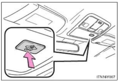
text_image
ITN16Y007Vehicles with smart entry & start system: Turn the "ENGINE START STOP" switch OFF and press the intrusion sensor cancel switch.
Vehicles without smart entry & start system: Turn the engine switch to the "LOCK" position and press the intrusion sensor cancel switch.
Pressing the switch again will re-enable the intrusion sensor.
To cancel the intrusion sensor, perform the necessary procedure each time canceling the sensor is desired.
System maintenance
The vehicle has a maintenance-free type alarm system.
Items to check before locking the vehicle
To prevent unexpected triggering of the alarm and vehicle theft, make sure of the following.
- Nobody is in the vehicle.
The windows is closed before the alarm is set. - No valuables or other personal items are left in the vehicle.
Triggering of the alarm
The alarm may be triggered in the following situations. (Stopping the alarm deactivates the alarm system.)

• The door is unlocked using the key.
- A person inside the vehicle opens a door or hood.
- The battery is recharged or replaced when the vehicle is locked.
■ When the battery is disconnected
Be sure to cancel the alarm system.
If the battery is disconnected before canceling the alarm, the system may be triggered when the battery is reconnected.
1-6. Theft deterrent system
- Alarm-operated door lock
- When the alarm is operating, the doors are locked automatically to prevent intruders.
- Do not leave the key inside the vehicle when the alarm is operating, and make sure the key is not inside the vehicle when recharging or replacing the battery.
■ Canceling and automatic re-enabling of the intrusion sensor
The alarm will still be set even when the intrusion sensor is canceled.
- Vehicles with smart entry & start system: After the intrusion sensor is canceled, pressing the "ENGINE START STOP" switch or unlocking the doors using the smart entry & start system or wireless remote control will re-enable the intrusion sensor.
Vehicles without smart entry & start system: After the intrusion sensor is canceled, turn the engine switch to the "LOCK" position or unlocking the doors using the wireless remote control will re-enable the intrusion sensor.
- The intrusion sensor will automatically be re-enabled when the alarm system is deactivated.
■ Intrusion sensor considerations
The sensor may trigger the alarm in the following situations.

natural_image
Illustration of a car exterior and a person standing beside it, no visible text or symbols- Persons or pets are in the vehicle.
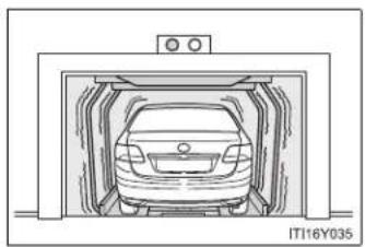
natural_image
Diagram of a car inside a storage tunnel, no text or symbols present- The vehicle is parked in a place where extreme vibrations or noises occur, such as in a parking garage.

natural_image
Illustration of two men inspecting a car with a windshield (no text or symbols visible)- Ice or snow is removed from the vehicle, causing the vehicle to receive repeated impacts or vibrations.

natural_image
Diagram of a car interior showing a meshed panel and seat structure (no text or symbols)- The wind or something similar causes a frost cover to move.
- Unstable items, such as dangling accessories or clothes hanging on the coat hooks, are in the vehicle.
A window is open.
● The vehicle is inside an automatic or high-pressure car washer. - The vehicle experiences impacts, such as hail, lightning strikes, or other kinds of repeated impacts or vibrations.
1-6. Theft deterrent system
Certification
Hereby, FUJITSU TEN LIMITED, declares that this FTL313 is in compliance with the essential requirements and other relevant provisions of Directive 1999/5/EC.
FUJITSU TEN LIMITED
Engineering Management Department
Design Management Division
Products Management Group
2-28, Gosho-dori 1-chome, Hyogo-ku, Kobe, 652-8510, Japan
Tel.: +81.78-682-2031 Fax.: +81.78-671-7160

DECLARATION of CONFORMITY
We, FUJITSU TEN LIMITED of the above address, hereby declare, at our sole responsibility, that the following product conforms to the Essential Requirements of the Radio and Telecommunications Terminal Equipment Directive 1999/5/EC in accordance with the tests conducted to the appropriate requirements of the relevant standards, as listed herewith.
Product Name:
Motion Sensor
Model Number:
FTL313
Reference Standards:
Radio :
EN 300 440-1 V1.5.1(2009-03)
EN 300 440-2 V1.3.1(2009-03)
EMC
EN 301 489-1 V1.8.1(2008-04)
EN 301 489-3 V1.4.1(2002-08)
Safety
EN 60065 2002+A11:2008
Supplementary Information:
| CE Mark | CE0891 |
| Member states intend for use | EU and EFTA |
| Member states with restrictive use | The sensor installed to vehicles sold other than UK and Ireland is not allowed to operate in UK |
Signature:

Position:
Department General Manager
Engineering Management Department
Design Management Division
Products Management Group
Date of issue:
20 April 2010
Place of issue:
Kobe, Japan

NOTICE
■ To ensure the system operates correctly
Do not modify or remove the system. If modified or removed, the proper operation of the system cannot be guaranteed.
1-7. Safety information
Correct driving posture
Drive with a good posture as follows:
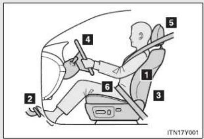
text_image
2 4 5 1 3 6 ITN17Y0011 Sit upright and well back in the seat. (→P. 98)
2 Adjust the position of the seat forward or backward to ensure the pedals can be reached and easily depressed to the extent required. (→P. 98)
3 Adjust the seatback so that the controls are easily operable.
4 Adjust the tilt and telescopic positions of the steering wheel downward so the airbag is facing your chest. (→P. 116)
5 Lock the head restraint in place with the center of the head restraint closest to the top of your ears. (→P. 106)
6 Wear the seat belt correctly. (→P. 108)

CAUTION
■ While driving
- Do not adjust the position of the driver's seat.
Doing so could cause the driver to lose control of the vehicle. - Do not place a cushion between the driver or passenger and the seatback. A cushion may prevent correct posture from being achieved, and reduce the effectiveness of the seat belt and head restraint, increasing the risk of death or serious injury to the driver or passenger.
- Do not place anything under the front seats.
Objects placed under the front seats may become jammed in the seat tracks and stop the seat from locking in place. This may lead to an accident. The adjustment mechanism may also be damaged.
■ Adjusting the seat position
- Do not recline the seat more than necessary when the vehicle is in motion, to reduce the risk of sliding under the lap belt.
If the seat is too reclined during an accident, the lap belt may slide past the hips and apply restraint forces directly to the abdomen or your neck may contact the shoulder belt, increasing the risk of death or serious injury.
Take care when adjusting the seat position to ensure that other passengers are not injured by the moving seat. - Do not put your hands under the seat or near the moving parts to avoid injury.
Fingers or hands may become jammed in the seat mechanism.
1-7. Safety information
SRS airbags
The SRS airbags inflate when the vehicle is subjected to certain types of severe impacts that may cause significant injury to the occupants. They work together with the seat belts to help reduce the risk of death or serious injury.
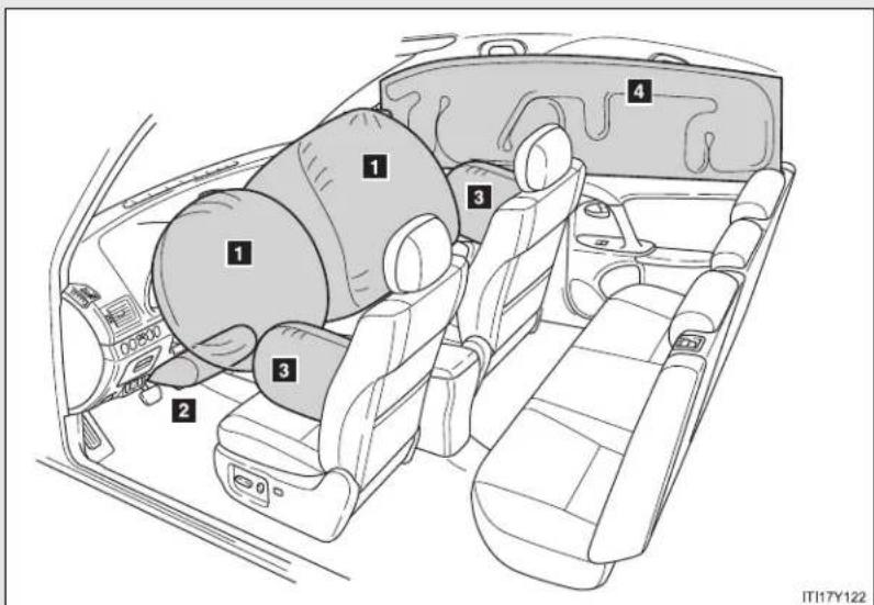
text_image
1 2 3 4 ITI17Y122▶ Front airbags
1 Driver airbag/front passenger airbag
Can help protect the head and chest of the driver and front passenger from impact with interior components.
2 Knee airbag
Can help provide driver protection.
▶ Side and curtain shield airbags
3 Side airbags
Can help protect the torso of the front seat occupants.
4 Curtain shield airbags
Can help protect primarily the head of front seat occupants and rear outboard seat occupants.
Airbag system components
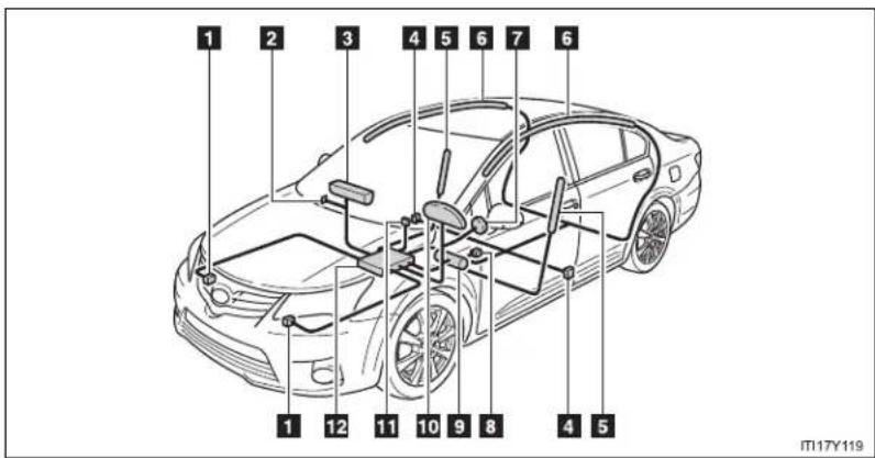
text_image
1 2 3 4 5 6 7 6 1 12 11 10 9 8 4 5 M17Y1191 Front airbag sensor
2 Airbag manual on-off switch
3 Front passenger airbag
4 Side and curtain shield air-bag sensor
5 Side airbag
6 Curtain shield airbag
7 Driver airbag
8 Driver's seat belt buckle switch
9 Knee airbag
10 SRS warning light
11 "PASSENGER AIRBAG" indicator light
12 Airbag sensor assembly
The main SRS airbag system components are shown. The SRS airbag system is controlled by the airbag sensor assembly. The airbag sensor assembly consists of a safing sensor and an airbag sensor.
In certain types of severe frontal or side impacts, the SRS airbag system triggers the airbag inflators. A chemical reaction in the inflators quickly fills the airbags with non-toxic gas to help restrain the motion of the occupants.
■ If the SRS airbags deploy (inflate)
- Bruising and slight abrasions may result from contact with a deploying (inflating) SRS airbag.
● A loud noise and white powder will be emitted. - Parts of the airbag module (steering wheel hub, airbag cover and inflator) as well as the front seats, front pillar and roof side rail, may be hot for several minutes. The airbag itself may also be hot.
The windshield may crack.
- Operating conditions (front airbags)
- The SRS front airbag will deploy in the event of an impact that exceeds the set threshold level (the level of force corresponding to an approximately 20 - 30 km/h [12 - 18 mph] frontal collision with a fixed wall that does not move or deform).
However, this threshold velocity will be considerably higher if the vehicle strikes an object, such as a parked vehicle or sign pole, which can move or deform on impact, or if the vehicle is involved in an underride collision (e.g. a collision in which the front of the vehicle “underrides”, or goes under, the bed of a truck, etc.).
- It is possible that in some collisions where the forward deceleration of the vehicle is very close to the designed threshold level, the SRS front airbags and the seat belt pretensioners may not activate together.
■ Operating conditions (side and curtain shield airbags)
The SRS side airbags and SRS curtain shield airbags will deploy in the event of an impact that exceeds the set threshold level (the level of force corresponding to the impact force produced by an approximately 1500 kg [3300 lb.] vehicle colliding with the vehicle cabin from a direction perpendicular to the vehicle orientation at an approximate speed of 20 - 30 km/h [12 - 18 mph]).
■ Conditions under which the SRS airbags may deploy (inflate), other than a collision
The SRS front airbags may also deploy if a serious impact occurs to the underside of your vehicle. Some examples are shown in the illustration.
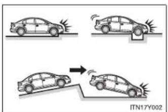
text_image
ITN17Y002- Hitting a curb, edge of pavement or hard surface
- Falling into or jumping over a deep hole
- Landing hard or vehicle falling
■ Types of collisions that may not deploy the SRS airbag (front airbags)
The SRS front airbags are generally not designed to inflate if the vehicle is involved in a side or rear collision, if it rolls over, or if it is involved in a low-speed frontal collision. But, whenever a collision of any type causes sufficient forward deceleration of the vehicle, deployment of the SRS front airbags may occur.
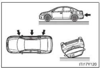
natural_image
Diagram showing three car top-down views with arrows indicating motion, no text or symbols present- Collision from the side
- Collision from the rear
- Vehicle rollover
1-7. Safety information
■ Types of collisions that may not deploy the SRS airbag (side airbags and curtain shield airbags)
The SRS side airbag and curtain shield airbag system may not activate if the vehicle is subjected to a collision from the side at certain angles, or a collision to the side of the vehicle body other than the passenger compartment.

natural_image
Top-down diagram of a car showing two side views with arrows indicating direction (no text or symbols)- Collision from the side to the vehicle body other than the passenger compartment
- Collision from the side at an angle
The SRS side airbags and curtain shield airbags are generally not designed to inflate if the vehicle is involved in a frontal or rear collision, if it rolls over, or if it is involved in a low-speed side collision.
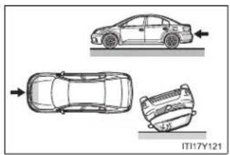
natural_image
Top-down diagram of a car showing front, side, and rear views with no text or symbols- Collision from the front
- Collision from the rear
- Vehicle rollover
■ When to contact any authorized Toyota dealer or repairer, or another duly qualified and equipped professional
In the following cases, contact any authorized Toyota dealer or repairer, or another duly qualified and equipped professional, as soon as possible.
• Any of the SRS airbags have been inflated.

natural_image
Top-down line drawing of a car (no text or symbols on the diagram itself)- The front of the vehicle is damaged or deformed, or was involved in an accident that was not severe enough to cause the SRS airbags to inflate.
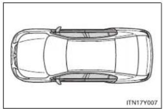
natural_image
Top-down line drawing of a car (no text or symbols on the diagram itself)- A portion of the doors is damaged or deformed, or the vehicle was involved in an accident that was not severe enough to cause the SRS side airbags and curtain shield airbags to inflate.
1-7. Safety information
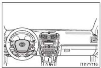
natural_image
Interior view of a car dashboard and steering wheel (no text or symbols visible)
natural_image
Line drawing of a car interior showing structural components and frame (no text or symbols)- The pad section of the steering wheel dashboard near the front passenger airbag or lower portion of the instrument panel is scratched, cracked, or otherwise damaged.
- The surface of the seats with the side airbag is scratched, cracked or otherwise damaged.
- The portion of the front, center and rear pillar garnish, or roof interior containing the curtain shield airbags inside is scratched, cracked or otherwise damaged.

CAUTION
■ SRS airbag precautions
Observe the following precautions regarding the airbags. Failure to do so may cause death or serious injury.
- The driver and all passengers in the vehicle must wear their seat belts properly.
The SRS airbags are supplemental devices to be used with the seat belts.
- The SRS driver airbag deploys with considerable force, and can cause death or serious injury especially if the driver is very close to the airbag.
Since the risk zone for the driver's airbag is the first 50 - 75 mm (2 - 3 in.) of inflation, placing yourself 250 mm (10 in.) from your driver airbag provides you with a clear margin of safety. This distance is measured from the center of the steering wheel to your breastbone. If you sit less than 250 mm (10 in.) away now, you can change your driving position in several ways:
- Move your seat to the rear as far as you can while still reaching the pedals comfortably.
- Slightly recline the back of the seat.
Although vehicle designs vary, many drivers can achieve the 250 mm (10 in.) distance, even with the driver seat all the way forward, simply by reclining the back of the seat somewhat. If reclining the back of your seat makes it hard to see the road, raise yourself by using a firm, non-slippery cushion, or raise the seat if your vehicle has that feature.
- If your steering wheel is adjustable, tilt it downward. This points the airbag toward your chest instead of your head and neck.
The seat should be adjusted as recommended above, while still maintaining control of the foot pedals, steering wheel, and your view of the instrument panel controls.

CAUTION
■ SRS airbag precautions
The SRS front passenger airbag also deploys with considerable force, and can cause death or serious injury especially if the front passenger is very close to the airbag. The front passenger seat should be as far from the airbag as possible with the seatback adjusted, so the front passenger sits upright.
- Improperly seated and/or restrained infants and children can be killed or seriously injured by a deploying airbag. An infant or child who is too small to use a seat belt should be properly secured using a child restraint system. Toyota strongly recommends that all infants and children be placed in the rear seats of the vehicle and properly restrained. The rear seats are the safest for infants and children. (→P. 168)
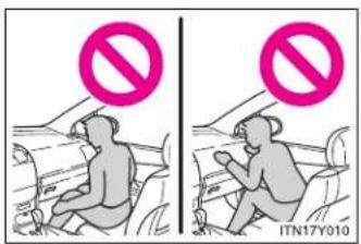
text_image
ITN17Y010- Do not sit on the edge of the seat or lean against the dashboard.
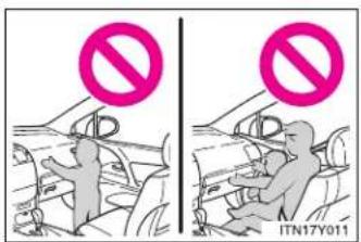
text_image
Two-panel image showing a person in a car with a 'no' symbol above their head, and another person in the background holding a sign.- Do not allow a child to stand in front of the SRS front passenger airbag unit or sit on the knees of a front passenger.
- Do not drive the vehicle while the driver or passenger has items resting on their knees.

CAUTION
■ SRS airbag precautions

text_image
ITN17Y012- Do not lean against the door, the roo side rail or the front, center and rear pillars.
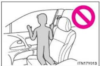
text_image
ITN17Y013- Do not allow anyone to kneel on the passenger seats toward the door or put their head or hands outside the vehicle.

text_image
IT117Y117- Do not attach anything to or lean anything against areas such as the dashboard, steering wheel pad or lower portion of the instrument panel. These items can become projectiles when SRS driver, front passenger and knee airbags deploy.

CAUTION
■ SRS airbag precautions
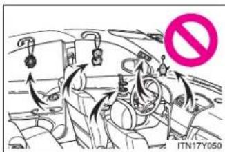
text_image
ITN17Y050Do not attach anything to areas such as the door, windshield glass, side door glass, front, center and rear pillars, roof side rail or assist grip. (Vehicles with emergency tire puncture repair kit: Except for the speed limit label →P. 685)
Do not hang coat hangers or other hard objects on the coat hooks. All of these items could become projectiles and seriously injure or kill you, should the SRS curtain shield airbag deploy.
- Vehicles without smart entry & star system: Do not attach any heavy, sharp or hard objects such as keys or accessories to the key. The objects may restrict the SRS knee airbag inflation or be thrust into the driver's seat area by the force of the deploying airbag, thus causing a danger.
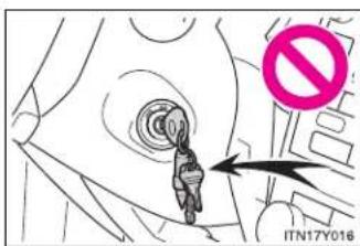
text_image
ITN17Y016- If the vinyl cover is put on the area where the SRS knee airbag will deploys, be sure to remove it.
- Do not use seat accessories which cover the parts where the SRS side airbags inflate as they may interfere with inflation of the airbags.
- Do not strike or apply significant levels of force to the area of the SRS airbag components shown on P. 157. Doing so can cause the SRS airbags to malfunction.
- Do not touch any of the component parts immediately after the SRS air bags have deployed (inflated) as they may be hot.

CAUTION
■ SRS airbag precautions
- If breathing becomes difficult after the SRS airbag has deployed, open a door or window to allow fresh air in, or leave the vehicle if it is safe to do so. Wash off any residue as soon as possible to prevent skin irritation.
- If the areas where the SRS airbags are stored, such as the steering wheel pad and front and rear pillar garnishes, are damaged or cracked, have them replaced by any authorized Toyota dealer or repairer, or another duly qualified and equipped professional.
■ Modification and disposal of SRS airbag system components
Do not dispose of your vehicle or perform any of the following modifications without consulting any authorized Toyota dealer or repairer, or another duly qualified and equipped professional.
The SRS airbags may malfunction or deploy (inflate) accidentally, causing death or serious injury.
- Installation, removal, disassembly and repair of the SRS airbags.
- Repairs, modifications, removal or replacement of the steering wheel, instrument panel, dashboard, seats or seat upholstery, front, center and rear pillars or roof side rail.
- Repairs or modifications of the front fender, front bumper, or side of the occupant compartment.
- Installation of snow plows, winches, etc. to the front grille (bull bars, kangaroo bar etc.).
Modifications to the vehicle's suspension system. - Installation of electronic devices such as RF-transmitter radios or CD players.
1-7. Safety information
Child restraint systems
Toyota strongly urges the use of child restraint systems.
Points to remember
Studies have shown that installing a child restraint system on a rear seat is much safer than installing one to the front passenger seat.
- Choose a child restraint system appropriate to the age and size of the child.
- For installation details, follow the instructions provided with the child restraint system.
General installation instructions are provided in this manual. - Toyota recommends that you use a child restraint system which conforms to the regulation "ECE No.44".
$$ (\rightarrow \mathrm{P}. 1 7 6) $$
Types of child restraints
Child restraint systems are classified into the following 5 groups according to the regulation "ECE No.44".
Group 0: Up to 10 kg (22 lb.) (0 - 9 months)
Group 0 ^+ : Up to 13 kg (28 lb.) (0 - 2 years)
Group I: 9 to 18 kg (20 to 39 lb.) (9 months - 4 years)
Group II: 15 to 25 kg (34 to 55 lb.) (4 years - 7 years)
Group III: 22 to 36 kg (49 to 79 lb.) (6 years - 12 years)
In this owner's manual, the following popular 3 types of child restraint systems that can be secured with the seat belts are explained.
▶ Baby seat
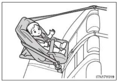
natural_image
Illustration of a child in a car seat inside a vehicle, no text or symbols presentEqual to Group 0 and 0 ^+ of "ECE No.44"
▶ Child seat

natural_image
Illustration of a child seated in a car seat, no text or symbols presentEqual to Group 0 ^+ and I of "ECE No.44"
▶ Junior seat

natural_image
Illustration of a child sitting in a car seatbelt, no text or symbols presentEqual to Group II and III of "ECE No.44"
Child restraint system suitability for various seating positions
Provided information in the table shows your child restraint system suitability for various seating positions.
| Mass groups\Seating position | Front passenger seat | Rear seat | ||
| Airbag manual on-off switch | ||||
| ON | OFF | Outside Center | ||
| 0Up to 10 kg(22 lb.)(0 - 9 months) | X Never put | U | U | U |
| 0^+ Up to 13 kg(28 lb.)(0 - 2 years) | X Never put | U | U | U |
| I9 to 18 kg(20 to 39 lb.)(9 months -4 years) | Rear-facing — X Never put | U | U | U |
| Forward-facing — UF | ||||
| II, III15 to 36 kg(34 to 79 lb.)(4 - 12 years) | U | F | U | U |
Key of letters inserted in the above table:
U: Suitable for “universal” category child restraint system approved for the use in this mass group.
UF: Suitable for forward-facing “universal” category child restraint system approved for the use in this mass group.
X: Not suitable seat position for children in this mass group.
The child restraint systems mentioned in the table may not be available outside of the EU area.
Other child restraint systems different from the systems mentioned in the table can be used, but the suitability of the systems must be carefully checked with the child restraint system manufacturer and retailer.
Child restraint system suitability for various seating positions (with ISOFIX rigid anchor)
Provided information in the table shows your child restraint system suitability for various seating positions.
| Mass groups Size | class Fixture | Vehicle ISOFIX positions | |
| Rear outside | |||
| Carrycot | F | ISO/L1 | X |
| G | ISO/L2 | X | |
| (1) X | |||
| Group 0Up to 10 kg (22 lb.)(0 - 9 months) | E | ISO/R1 | X |
| (1) X | |||
| Group 0+Up to 13 kg (28 lb.)(0 - 2 years) | E | ISO/R1 | X |
| D | ISO/R2 | X | |
| C | ISO/R3 | X | |
| (1) X | |||
| Group I9 to 18 kg(20 to 39 lb.)(9 months - 4 years) | D | ISO/R2 | X |
| C | ISO/R3 | X | |
| B | ISO/F2 | IUF | |
| B1 | ISO/F2X | IUF | |
| A | ISO/F3 | IUF | |
| (1) X | |||
| Group II15 to 25 kg(34 to 55 lb.) | (1) X | ||
| Group III22 to 36 kg(49 to 79 lb.) | (1) X |
(1) For the CRS which do not carry the ISO/XX size class identification (A to G), for the applicable mass group, the car manufacturer shall indicate the vehicle specific ISOFIX child restraint system(s) recommended for each position.
Key of letters inserted in the above table:
IUF: Suitable for ISOFIX forward-facing child restraint systems of universal category approved for use in this mass group.
X: ISOFIX position not suitable for ISOFIX child restraint systems in this mass group and/or this size class.
The child restraint systems mentioned in the table may not be available outside of the EU area.
Other child restraint systems different from the systems mentioned in the table can be used, but the suitability of the systems must be carefully checked with the child restraint system manufacturer and retailer.
■ When installing the child restraint system on the front passenger seat
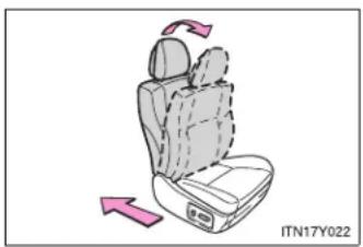
natural_image
Illustration of a car seat with directional arrows indicating rotation (no text or symbols)When you have to use a child restraint system on the front passenger seat, adjust the following:
- The seatback to the most upright position
● The seat cushion fully rearward position
1-7. Safety information
- Selecting an appropriate child restraint system
Get an appropriate child restraint system for the child. If a child is too large for a child restraint system, sit the child on a rear seat and use the vehicle's seat belt. (→P. 108)

CAUTION
■ Using a child restraint system
The use of a child restraint system not suitable for the vehicle may not properly secure the infant or child, resulting in serious injury or even death.
■ Child restraint precautions
For effective protection in automobile accidents and sudden stops, a child must be properly restrained, using a seat belt or child restraint system depending on the age and size of the child. Holding a child in your arms is not a substitute for a child restraint system. In an accident, the child can be crushed against the windshield, or between you and the vehicle's interior.
Toyota strongly urges the use of a proper child restraint system that conforms to the size of the child, installed on the rear seat. According to accident statistics, the child is safer when properly restrained in the rear seat than in the front seat.
- Never install a rear-facing child restraint system on the front passenger seat when the airbag manual on-off switch is "ON". (→P. 190)
In the event of an accident, the force of the rapid inflation of the front passenger airbag can cause death or serious injury to the child.

CAUTION
■ Child restraint precautions
A forward-facing child restraint system should allowed to be installed on the front passenger seat only when it is unavoidable. Always move the seat as far back as possible, because the front passenger airbag could inflate with considerable speed and force. Otherwise, the child may be killed or seriously injured.
- Do not allow the child to lean his/her head or any part of his/her body against the door or the area of the seat, front and rear pillars or roof side rail from which the side airbags or curtain shield airbags deploy even if the child is seated in the child restraint system. It is dangerous if the side airbags and curtain shield airbags inflate, and the impact could cause death or serious injury to the child.
- Make sure you have complied with all installation instructions provided by the child restraint manufacturer and that the system is properly secured. If it is not secured properly, it may cause death or serious injury to the child in the event of a sudden stop, sudden swerve or an accident.
■ When children are in the vehicle
Do not allow children to play with the seat belt. If the seat belt becomes twisted around a child's neck, it may lead to choking or other serious injuries that could result in death.
If this occurs and the buckle cannot be unfastened, scissors should be used to cut the belt.
■ When the child restraint system is not in use
- Keep the child restraint system properly secured on the seat even if it is not in use. Do not store the restraint unsecured in the passenger compartment.
- If it is necessary to detach the child restraint system, remove it from the vehicle or store it securely in the trunk/luggage compartment. This will prevent it from injuring passengers in the event of a sudden stop, sudden swerve or accident.
1-7. Safety information
Installing child restraints
Follow the child restraint system manufacturer's instructions. Firmly secure the child restraints to the seats using a seat belt or a ISOFIX rigid anchor (ISOFIX child restraint system). Attach the top strap when installing a child restraint system.
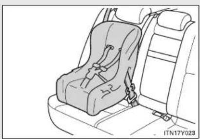
natural_image
Line drawing of a car seat assembly with no text or symbolsSeat belts (An ELR belt requires a locking clip.)
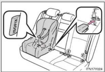
text_image
ISOFIX ITN17Y024ISOFIX rigid anchor (ISOFIX child restraint system)
These exclusive fixing bars are provided for the outside rear seats. (Tags displaying the location of the anchors are attached to the seats.)
▶ Sedan
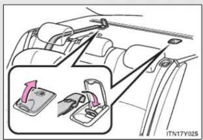
text_image
ITN17Y025Anchor bracket (for top strap)
Anchor brackets are provided for outside rear seats.
Wagon

text_image
ITN17Y0461-7. Safety information
Installing child restraints using a seat belt
■ Rear-facing — Baby seat/child seat

natural_image
Line drawing of a car seat assembly with no text or symbolsPlace the child restraint system on the rear seat facing the rear of the vehicle.
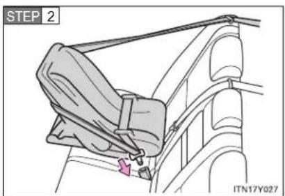
text_image
STEP 2 ITN17Y027Run the seat belt through the child restraint system and insert the plate into the buckle. Make sure that the belt is not twisted. Keep the lap portion of the belt tight.
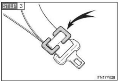
text_image
STEP 3 ITN17Y928Install a locking clip near the tab of the lap and shoulder belt by inserting the lap and shoulder webbing through the recesses of the locking clip.
■ Forward-facing — Child seat
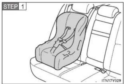
natural_image
Line drawing of a car seat assembly with no text or symbolsPlace the child restraint system on the seat facing the front of the vehicle.
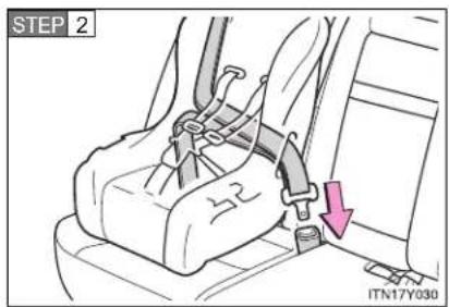
text_image
STEP 2 ITN17Y030Run the seat belt through the child restraint system and insert the plate into the buckle. Make sure that the belt is not twisted. Keep the lap portion of the belt tight.

text_image
STEP 3 ITN17Y028Install a locking clip near the tab of the lap and shoulder belt by inserting the lap and shoulder webbing through the recesses of the locking clip.
1-7. Safety information
Junior seat
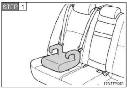
natural_image
Line drawing of a car seatbelt with a strap, labeled STEP 1 (no text or symbols on the diagram itself)Place the child restraint system on the seat facing the front of the vehicle.
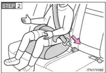
text_image
STEP 2 ITN17Y032Sit the child in the child restraint system. Fit the seat belt to the child restraint system according to the manufacturer's instructions and insert the plate into the buckle. Make sure that the belt is not twisted.
Check that the shoulder belt is correctly positioned over the child's shoulder, and that the lap belt is as low as possible.
(→P. 108)
Removing a child restraint system installed with a seat belt
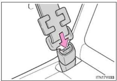
text_image
C SENGA ITN17Y033Push the buckle release button and fully retract the seat belt.
Installation with ISOFIX rigid anchor (ISOFIX child restraint system)
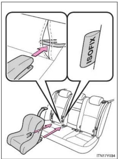
text_image
ISOFIX ITN17Y034Check the positions of the exclusive fixing bars, and install the child restraint system to the seat.
If the child restraint has a top strap, the top strap should be latched onto the anchors.
1-7. Safety information
Child restraint systems with a top strap
STEP 1 Secure the child restraint system using a seat belt or ISOFIX rigid anchors, and do the following.
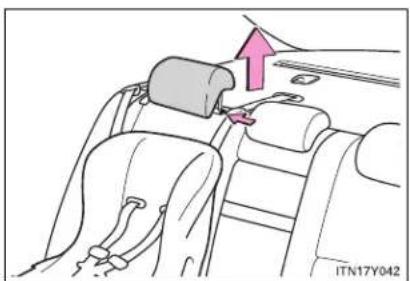
natural_image
Diagram of a car seatbelt buckle assembly with a hand adjusting the seat (no text or symbols present)Remove the head restraint.
(→P. 106)
STEP 2 Open the anchor bracket cover, latch the hook onto the anchor bracket and tighten the top strap.
▶ Sedan
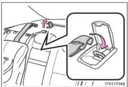
text_image
ITN17Y043Make sure the top strap is securely latched.
Wagon
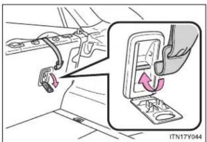
natural_image
Car interior view showing seatbelt clamps and a close-up of the seatbelt switch (no text or symbols visible)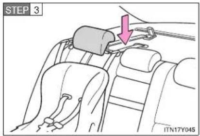
text_image
STEP 3 ITN17Y045Replace the head restraint to the upmost position.
- When installing a child restraint system in the front passenger's seat or rear seat
You need a locking clip to install the child restraint system. Follow the instructions provided by the manufacturer of the system. If your child restraint system does not provide a locking clip, you can purchase the following item from any authorized Toyota dealer or repairer, or another duly qualified and equipped professional.
Locking clip for child restraint system (Part No. 73119-22010)

CAUTION
■ When installing a child restraint system
Follow the directions given in the child restraint system installation manual and fix the child restraint system securely in place.
If the child restraint system is not correctly fixed in place, the child or other passengers may be seriously injured or even killed in the event of sudden braking, sudden swerving or an accident.
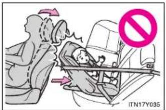
text_image
ITN17Y035- If the driver's seat interferes with the child restraint system and prevents it from being attached correctly, attach the child restraint system to the right-hand rear seat (left-hand drive vehicles) or the left-hand rear seat (right-hand drive vehicles).

natural_image
Illustration of a child seated in a car seat, with no visible text or symbols- When installing a forward-facing child restraint on the front passenger seat, move the seat as far back as possible. Failing to do so may result in death or serious injury if the airbags deploy (inflate).

CAUTION
■ When installing a child restraint system
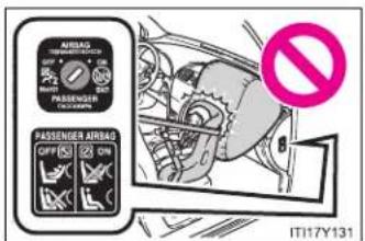
text_image
AIRSAG TEMPORARY SWITCH 2 PASSENGER AIRBAG OFF ② ON IT17Y131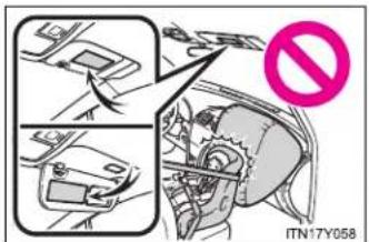
text_image
ITN17Y058- Never install a rear-facing child restrain system on the front passenger seat when the airbag manual on-off switch is "ON". (→P. 190)
The force of the rapid inflation of the front passenger airbag can cause death or serious injury to children in the event of an accident.
There is a sticker on the passenger side of the instrument panel and a label on both sides of the passenger side sun visor, both indicating it is forbidden to attach a rear-facing child restraint system to the front passenger seat.
Details of the label on the passenger side sun visor are shown in the illustrations below. The label includes information written in the language of your country.

CAUTION
■ When installing a child restraint system
▶ Type A
| WARNING AVERTISSEMENT WARNUNG AVVISO ADVERTENCIA WAARSCHUWING | |
 | DO NOT place a rear facing child seat on the front seat unless the passengerairbag is deactivated. DEATH OR SERIOUS INJURY can occur. See owner's manual.NE JAMAIS placer un siège enfant positionné dos à la route sur le siège avant,sauf si l'airbag passager est désactivé. Risque de MORT OU BLESSURÉ GRAVE.Voir le manuel du propriétaire.KEINEN rückwärtsgerichteten Kindersitz auf dem Vordersitz verwenden, außer derBefahrer-Airbag ist deaktiviert. TOD ODER SCHWERE VERLETZUNGEN könnendie Folge sein. Siehe Betriebsanleitung.NON posizionare le seggiolino per bambini rivolto in senso opposto a quello di marcia sul sedile anteriore se l'airbag del passeggero non e'stato disattivato. Rischio di MORTE O LESIONI GRAVI. Consultare il manuale di uso e manutenzione.NO coloque una silla para niños en sentido contrario al de la marcha del vehículoen el asiento del acompañante, excepto si el airbag del pasajero estuviera desactivado.Riesgo de MUERTE O HERIDAS GRAVES. Consulte el manual del propietario.GEEN tegen de rijrichting in geplaatst kinderzitje op de voorstoel plaatsen.tenzij de passagiersairbag gedeactiveerd is. DOOD OF ZWARE VERWONDINGENkunnen het gevolg zijn. Zie instruktleboekje. |
IT17Y126
▶ Type B
 | WARNING ADVARSEL VAROITUS AVISO ΠΡΟΣΟΧΗ WARNING | |
| G DO NOT place a rear facing child seat on the front seat unless the passengerB airbag is deactivated. DEATH OR SERIOUS INJURY can occur. See owner's manual. | ||
| Placer ALDRIG et bagudvendt barnesæde på forsædet, uden at passagersædets | ||
| airbag er frakoblet. Risiko for D∅D ELLER ALVORLIG PERSONSKADE.Se instruktionsbog. | ||
| ÄLÄ aseta etuistuimelle seikä menosuuntaan asennettavaa lasten turvaistuinta silloin,kun matkustajan turvatynyä ei ole kytketty pois toiminnasta. Seurauksena voi ollaKUOLEMA TAI VAKAVA LOUKKAANTUMINEN. Katso lisäohjeet omistajan käsikirjasta. | ||
| NÃO instale uma cadeirinha para crianças voltada para trås no banco da frente semdasactivar o aibag do passageiro. Risco de MORTE OU FERIMENTOS GRAVES.Consulte o manual do proprietário. | ||
| MHN TOTTOBETEITE TTAÏDIKÖ KÄTHIŞMA OTTÍSÎIOU TTPOOANATOLISMOÜ STO MTIPROSTIVÖ KÄTHIŞMA ,EKTOŠ AV iEVAI ATTEVEPYOTTOINJÉVOS O AEPÓNAKOS CUNVOÏNYOU. EVOËXETAI VA TTPOKLYHÉIΘANATOŠ 'H ΣOBAPOŠ TPAYMATIÉMOŠ. ΣυμβουLETUÉITE TO βιβLIO OÔNYIών XPHÖNÇ. | ||
| DU FÄR ALDRIG placera en bakätvänd barnstol i framsätet, om inte passagerarkrockkudden är avaktiverad. DÖDSFALL ELLERALLVARLIGA PERSONSKADOR kan inträffa. Se instruktionsbok. | ||
IT17Y127

CAUTION
■ When installing a child restraint system
▶ Type C
| ⚠ WARNING AVISO ΠΡΟΣΟΧΗ ATΕΝΤΙΟΝΑRE ΒΗΜΙΛΗΜΕ UYARI | |
 | DO NOT place a rear facing child seat on the front seat unless the passenger airbag is deactivated. DEATH OR SERIOUS INJURY can occur. See owner's manual.NÃO instale uma cadeirinha para crianças voltada para trás no banco da frente sem dasactivar o airbag do passageiro. Risco de MORTE OU FERIMENTOS GRAVES.Consulte o manual do proprietário.MHN τοποθετείτε ποϊδικό κάθισμα οπίσθιου προσανατολισμού στο μπροστινό κάθισμα, εκτός αν είναι απενεργοποιημένος ο αερόσακος συνοήγνού. Ενδέχεται να προκλήθεί ΘΑΝΑΤΟΣ ́Н ΣΟΒΑΡΟΣ ΤΡΑΥΜΑΤΙΣΜΟΣ. Συμβουλετείτε το βίβλίο οδηγιών χρήσης.NU montaji pe scaunul din fajã scaunul pentru copil orientat cu spatele la sensul de mers decât dacă airbag-ul pentru pasager este dezactivat. Nerespectarea acestei reguli poate provoca MOARTEA SAU RĂNIREA GRAVĂ A COPILULUL. Vezi manualul utilizatorului.HE поставайте объяснato назад детско столче върху предната седалка, освен ако въдушната вызглавница за пътника не е деактмвирана. Неспазването на това условие може да доведе до СМЪРТ ИЛИ СЕРИОЗНО НАРАНЯВАНЁ. За повече информация викте инструкцията за експлоатация.Yolcu hava yastigi devre dışı bırakίπαΜισίψα, yüzü gerlye bakan çocuk güvenlik koltuğunu ASLA ön koltuğa KOYMAYIN. ŐLÜME VEYA CIDDI YARALANMALARA sebebiyet verebilir. Kullanıcı el kitabina bakınız. |
IT17Y128
▶ Type D
| ⚠️ Предупреждение OSTRZEŻENIE VÝSTRAHA VAROVANIE FIGYELMEZTETÉS OPOZORILO | |
| ΗΕ УСТАНАВЛИВАЙТЕ детские креспа на переднее сиденье в направлении. противоположном движению автомобиля, если подушка безопасности пассажира не отключена. Результатом могут быть ТЯЖЕЛЫЕ ТРАВМЫ ИЛИ ЛЕТАЛЬНЫЙ ИХСЬОД. Смотрите руководство для Владельца. | |
| NIGDY NIE wolno umieszcaźć na przednim siedzeniu samochodowego fotelika dzieclęcego, mocowanego tyjem do kierunku jazdy. jeżeli nie zostata odlączona poduszka powietrzna pasażera. Może dojść do ŠMIERCI LUB PÓWAŹNEGO OBRĄŻENIA ČIAŁA. Patrz Instrukcja obsługi. | |
| NEUMÍŠTŮJTE dětskou sedačku směřující proti směru jizdy na předníl sedadlo, pokud není airbag spolujezdce deaktivován. Mohlo by dojit K VAŽNĚMU NEBO SMRTELNĚMU PORANĚNÍ. Víz uživatelská přiručka. | |
| ZÁKAZ UMIESTNENIA detskej sedačky na prednom sedadle proti, smeru jazdy, pokiaľ nie je deaktivovaný airbag spolujazcá. Hroži NEBEZPEČENSTVO SMRTIALEBO VAŽNEHO ZRĂNENIA. Pozri priručku uživateľa. | |
| TILOS az első utasálísre hátrafelé néző gyermekülést helyezni, amjíg az utasoldali légzsákot nem hatástalanították. HALÁLT VAGY SULYOS SÉRÚLEST okozhat. További információkat a kezelési útmutatóban talál. | |
| NE NAMEŠĆAJTE otroškega sedeža, v katerem sedi otrok s hrbtom obrmjen v smer vožnje, na sprednji sedež, će sovoznikova varnostna blazina ni izklopljena. Lahko bi prišlo do RESNE POŠKODBE ALI SMRTI. Prosimo, preberite navodila za uporabo. | |
IT17Y129

CAUTION
■ When installing a child restraint system
▶ Type E
 | |SPÉJIMAS HOIATUS BRÍDINÁJUMS ADVARSEL VAROITUS VARNING |
| NETVIRTINKÍTE | galá atsuktos vaiklškos automobilinés kédutés ant priekinés keleivio sédynés jei neljsjungta oro pagalvé - GALÍTE RIMTAI AR MIRTÍNAI sužaloti kédutéje sêhdínj vaiką Žr.Instrukciją automobilio savininkui. | |
| ÄRGE asetage sejaga söldusuunas olevat lapse turvatooli esljstmele, välja arvatud juhul, kul kaassõitja turvapadi on välja lültatud. Tagajärjeka vôib olla SURM VOI TÓSINE VIGÁSTUS. Vaadake omaniku käsiraamatut. | |
| NENOVIETOJIET uz aizmuguri věrstu běmą sõdeklīti uz priekšējā sõdekja, izņemot, ja ir dezaktivizēts pasažiera gasa spilvens. Tas var izraisīt NAVI VAI NOPIETNU SAVAINÓJUMU. Skatiet lietotāja rokasgrāmatu. | |
| Placer ALDRIG et bagudvendt barnesæde på forsædet, uden at passagersædets airbag er frakoblet. Risiko for DØD ELLER ALVORLIG PERSONSKADE.Se instruktionsbog. | |
| ÄLÄ aseta etuistimelle selkä menosuntaan asennettavaa lasten turvaistuinta silloin, kun matkustajan turvatyynyä ei ole kytketty pois toiminnasta. Seurauksena voi olla KUOLEMA TAI VAKAVA LOUKKAANTUMINEN. Katso lisäohjeet omistajan käsikirjasta. | |
| DU FÄR ALDRIG placera en bakätvänd bamstol i framsätet, om inte passagerar krockkudden är avaktiverad. DÖDSFALL ELLER ALLVARLIGA PERSONSKADOR kan inträffa. Se instruktionsbok. |
IT17Y130
- When a junior seat is installed, always ensure that the shoulder belt is positioned across the center of the child's shoulder. The belt should be kept away from the child's neck, but not so that it could fall off the child's shoulder. Failing to do so may result in death or serious injury in the event of sudden braking, sudden swerving or an accident.

CAUTION
■ When installing a child restraint system
- Ensure that the belt and tab are securely locked and the seat belt is not twisted.
- Shake the child restraint left and right, and forward and back to ensure that it has been securely installed.
- Follow all installation instructions provided by the child restraint system manufacturer.
■ To correctly attach a child restraint system to the anchors
When using the ISOFIX rigid anchors, be sure that there are no foreign objects around the anchors and that the seat belt is not caught behind the child restraint system. Make sure the child restraint system is securely attached, or it may cause death or serious injury to the child or other passengers in the event of a sudden stop, sudden swerve or accident.
1-7. Safety information
Airbag manual on-off system
This system deactivates the front passenger airbag.
Only deactivate the airbag when using a child restraint system on the front passenger seat.

text_image
PASSENGER AIRBAG ON IT117Y118"PASSENGER AIRBAG" indicator
This indicator turns on when the airbag system is ON.
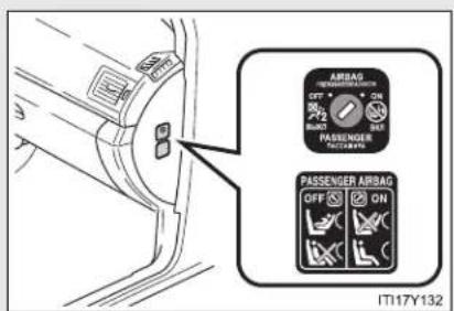
text_image
AIRBAG OFF + AIRBAG ON PASSenger OFF ON PASSENGER AIRBAG OFF ON IT17Y132Airbag manual on-off switch
Deactivating the front passenger airbag

text_image
AIRBAG OFF ON PASSING PASSENG PASSENG ENGER BAG OFF IT17Y133Insert the key into the cylinder and rotate to the "OFF" position.
The "OFF" indicator turns on.
The indicator turns on when
▶ Vehicles with smart entry & start system
Only when the "ENGINE START STOP" switch is in IGNITION ON mode.
▶ Vehicles without smart entry & start system
Only when the engine switch is in the "ON" position.
■ "PASSENGER AIRBAG" indicator information
If any of the following problems occurs, it is possible that there is a malfunction in the system. Have the vehicle inspected by any authorized Toyota dealer or repairer, or another duly qualified and equipped professional.
- Neither "ON" nor "OFF" comes on.
- The indicator does not change when the airbag manual on-off switch is switched to "ON" or "OFF" position.

CAUTION
■ When installing a child restraint system
For safety reasons, always install the child restraint system in a rear seat. In the event that the rear seat cannot be used, the front seat can be used as long as the airbag manual on-off system is set to "OFF". If the airbag manual on-off system is left "ON", the strong impact of the airbag deployment (inflation) may cause serious injury or even death.
■ When a child restraint system is not installed on the front passenger seat
Ensure that the airbag manual on-off system is set to "ON". If it is left "OFF", the airbag may not deploy in the event of an accident, which may result in serious injury or even death.
1-7. Safety information
When driving
2
2-1. Driving procedures
Driving the vehicle 194
Engine (ignition) switch (vehicles with smart entry & start system)..... 210
Engine (ignition) switch (vehicles without smart entry & start system)..... 215
Multidrive 219
Automatic transmission .... 225
Manual transmission..... 232
Turn signal lever 236
Parking brake 237
Horn 241
2-2. Instrument cluster
Gauges and meters ..... 242
Indicators and warning lights 245
Multi-information display 249
2-3. Operating the lights and wipers
Headlight switch.... 262
Fog light switch 267
Windshield wipers and washer 269
Rear window wiper and washer (wagon) ..... 274
2-4. Using other driving systems
Cruise control.... 275
Dynamic radar cruise control.... 281
Speed limiter 300
Toyota parking assist-sensor .... 303
Rear view monitor system 308
LKA (Lane-Keeping Assist).... 318
Driving assist systems ..... 327
PCS (Pre-Crash Safety) 333
2-5. Driving information
Cargo and luggage 342
Winter driving tips 344
Trailer towing 348
2-1. Driving procedures
Driving the vehicle
The following procedures should be observed to ensure safe driving.
■ Starting the engine ( P. 210, 215)
Driving
▶ Multidrive or automatic transmission
STEP 1 With the brake pedal depressed, shift the shift lever to "D" or "M". (→P. 219, 225)
STEP 2 Release the parking brake. (→P. 237)
STEP 3 Gradually release the brake pedal and gently depress the accelerator pedal to accelerate the vehicle.
▶ Manual transmission
STEP 1 With the clutch pedal fully depressed, shift the shift lever to "1". (→P. 232)
STEP 2 Release the parking brake. ( P. 237)
STEP 3 Gradually release the clutch pedal. At the same time, gently depress the accelerator pedal to accelerate the vehicle.
Stopping
▶ Multidrive or automatic transmission
STEP 1 With the shift lever in "D" or "M", depress the brake pedal.
STEP 2 If necessary, set the parking brake.
When the vehicle is stopped for an extended period of time, shift the shift lever to "P" or "N". (→P. 219, 225)
▶ Manual transmission
STEP 1 With the clutch pedal fully depressed, depress the brake pedal.
STEP 2 If necessary, set the parking brake.
When the vehicle is stopped for an extended period of time, shift the shift lever to "N". (→P. 232)
Parking the vehicle
▶ Multidrive or automatic transmission
STEP 1 With the shift lever in "D" or "M", depress the brake pedal.
STEP 2 Set the parking brake. (→P. 237)
STEP 3 Shift the shift lever to "P". (→P. 219, 225)
When parking on a hill, if necessary, block the wheels.
STEP 4 Vehicles with smart entry & start system: Turn the "ENGINE START STOP" switch OFF and stop the engine.
Vehicles without smart entry & start system: Turn the engine switch to the "LOCK" position and stop the engine.
STEP 5 Lock the door, making sure that you have the key on your person.
2-1. Driving procedures
▶ Manual transmission
STEP 1 With the clutch pedal fully depressed, depress the brake pedal.
STEP 2 Set the parking brake. ( P. 237)
STEP 3 Shift the shift lever to "N". (→P. 232)
When parking on a hill, shift the shift lever to "1" or "R". If necessary, block the wheels.
STEP 4 Vehicles with smart entry & start system: Turn the "ENGINE START STOP" switch to OFF and stop the engine.
Vehicles without smart entry & start system: Turn the engine switch to the "LOCK" position and stop the engine.
STEP 5 Lock the door, making sure that you have the key on your person.
Starting on a steep uphill
▶ Multidrive or automatic transmission
STEP 1 Firmly set the parking brake and shift the shift lever to "D" or "M".
STEP 2 Gently depress the accelerator pedal.
STEP 3 Release the parking brake.
▶ Manual transmission
STEP 1 With the parking brake set and the clutch pedal fully depressed, shift the shift lever to "1".
STEP 2 Lightly depress the accelerator pedal at the same time as gradually releasing the clutch pedal.
STEP 3 The parking brake will automatically release. (→P. 237)
- Driving in the rain
- Drive carefully when it is raining, because visibility will be reduced, the windows may become fogged-up, and the road will be slippery.
- Drive carefully when it starts to rain, because the road surface will be especially slippery.
- Refrain from high speeds when driving on an expressway in the rain, because there may be a layer of water between the tires and the road surface, preventing the steering and brakes from operating properly.
■ Engine speed while driving (vehicles with Multidrive or automatic transmission)
In the following conditions, the engine speed may become high while driving. This is due to automatic up-shifting control or down-shifting implementation to meet driving conditions. It does not indicate sudden acceleration.
● The vehicle is judged to be driving uphill or downhill
- When the accelerator pedal is released
2-1. Driving procedures
■ Breaking in your new Toyota
To extend the life of the vehicle, the following precautions are recommended to observe:
- For the first 300 km (200 miles): Avoid sudden stops.
-
For the first 800 km (500 miles): Do not tow a trailer.
For the first 1000 km (600 miles): -
Do not drive at extremely high speeds.
- Avoid sudden acceleration.
- Do not drive continuously in the low gears.
- Do not drive at a constant speed for extended periods.
■ Eco Driving Indicator Light (if equipped)
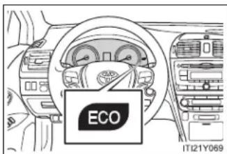
text_image
ECO IT121Y069During Eco-Friendly acceleration (Eco-driving), Eco Driving Indicator Light will turn on. When the acceleration exceeds Zone of Eco driving, and when the vehicle is stopped, the light turns off.
Eco Driving Indicator Light will not operate in the following conditions:
- The shift position is anything other than "D"
- The vehicle is being driven in "SPORT" mode (→P. 220, 226)
- If equipped, the paddle shift switch is operated while the shift position is "D"
- The vehicle speed is approximately 130 km/h (80 mph) or higher
- Idling time before engine stop (diesel engine)
To prevent damage to the turbocharger, allow the engine to idle immediately after high-speed driving or hill climbing.
| Driving condition Idling time | ||
| Normal city driving Not necessary | ||
| High-speed driving | Constant speed of approx. 80 km/h (50 mph) | Approximately 20 seconds |
| Constant speed of approx. 100 km/h (62 mph) | Approximately 1 minute | |
| Steep hill driving or continuous driving at 100 km/h (62 mph) or more (race track driving etc.) | Approximately 2 minutes | |
- Operating your vehicle in a foreign country
Comply with the relevant vehicle registration laws and confirm the availability of the correct fuel. ( P. 725)
■ When driving up steep hills in high temperature conditions
Engine output may be intentionally restrained on vehicles with the 2AD-FHV engine and automatic transmission to protect the engine and its components. Following may occur, but they do not indicate a malfunction:
- You may experience a drop in speed.
● Air conditioning system control may be changed.
For example, the button to switch between outside air mode and recirculated air mode will be fixed in recirculated air mode.

CAUTION
■ When starting the vehicle (vehicles with a Multidrive or automatic transmission)
Always keep your foot on the brake pedal while stopped with the engine running. This prevents the vehicle from creeping.
■ When driving the vehicle
- Do not drive if you are unfamiliar with the location of the brake and accelerator pedals to avoid depressing the wrong pedal.
- Accidentally depressing the accelerator pedal instead of the brake pedal will result in sudden acceleration that may lead to an accident that could result in death or serious injury.
- When backing up, you may twist your body around, leading to a difficulty in operating the pedals. Make sure to operate the pedals properly.
- Make sure to keep a correct driving posture even when moving the vehicle only slightly, allowing you to depress the brake and accelerator pedals properly.
- Depress the brake pedal using your right foot. Depressing the brake pedal using your left foot may delay response in an emergency, resulting in an accident.
- Do not drive the vehicle over or stop the vehicle near flammable materials. The exhaust system and exhaust gases can be extremely hot. This may cause a fire if there is any flammable material nearby.
- Vehicles with a Multidrive or automatic transmission: Do not let the vehicle roll backwards while the shift lever is in a driving position, or roll forward while the shift lever is in "R".
Doing so may cause the engine to stall or lead to poor brake performance, resulting in an accident or damage to the vehicle.

CAUTION
- If the smell of exhaust is noticed inside the vehicle, open the windows and check that the trunk or back door is closed.
Large amounts of exhaust in the vehicle can cause driver drowsiness and an accident, resulting in death or a serious health hazard. Have the vehicle inspected by any authorized Toyota dealer or repairer, or another duly qualified and equipped professional immediately. - On vehicles with a Multidrive or automatic transmission, do not shift the shift lever to "P" while the vehicle is moving.
Doing so can damage the transmission and may result in a loss of vehicle control. - Do not shift the shift lever to "R" while the vehicle is moving forward.
Doing so can damage the transmission and may result in a loss of vehicle control. - Do not shift the shift lever to "D" (vehicles with a Multidrive or automatic transmission) or "1" (vehicles with a manual transmission) while the vehicle is moving backward.
Doing so can damage the transmission and may result in a loss of vehicle control. - Moving the shift lever to "N" while the vehicle is moving will disengage the engine from the transmission. Engine braking is not available when "N" is selected.
- During normal driving, do not turn off the engine. Turning the engine off while driving will not cause loss of steering or braking control, but the power assist to these systems will be lost. This will make it more difficult to steer and brake, so you should pull over and stop the vehicle as soon as it is safe to do so.
However, in the event of an emergency, such as if it becomes impossible to stop the vehicle in the normal way: P. 716

CAUTION
- Use engine braking (downshift) to maintain a safe speed when driving down a steep hill.
Using the brakes continuously may cause the brakes to overheat and lose effectiveness. ( P. 220, 226) - When stopped on an inclined surface, use the brake pedal and parking brake to prevent the vehicle from rolling backward or forward and causing an accident.
- Do not adjust the position of the steering wheel, the seat, or the inside or outside rear view mirrors while driving.
Doing so may result in a loss of vehicle control that can cause accidents that may result in death or serious injury.
● Always check that all passengers' arms, heads or other parts of their bodies are not outside the vehicle, as this may result in death or serious injury. - Sudden braking, acceleration and steering may cause tire slippage and reduce your ability to control the vehicle, resulting in an accident.
- Sudden acceleration, engine braking due to shift changing, or changes in engine speed could cause the vehicle to skid, resulting in an accident.
After driving through a puddle, lightly depress the brake pedal to make sure that the brakes are functioning properly. Wet brake pads may prevent the brakes from functioning properly. If the brakes on only one side are wet and not functioning properly, steering control may be affected, resulting in an accident.

When driving on slippery road surfaces

CAUTION
■ When shifting the shift lever (vehicles with a Multidrive or automatic transmission)
Be careful not to shift the shift lever with the accelerator pedal depressed. This may lead to unexpected rapid acceleration of the vehicle that may cause an accident and result in death or serious injury.
■ When the vehicle is stopped
- Do not race the engine.
If the vehicle is in any shift positions other than "P" (vehicles with a Multidrive or automatic transmission) or "N", the vehicle may accelerate suddenly and unexpectedly, and may cause an accident. - Do not leave the vehicle with the engine running for a long time.
If such a situation cannot be avoided, park the vehicle in an open space and check that exhaust fumes do not enter the vehicle interior. - Vehicles with a Multidrive or automatic transmission: In order to prevent accidents due to the vehicle rolling away, always keep depressing the brake pedal while the engine is running, and apply the parking brake as necessary.
- If the vehicle is stopped on an incline, in order to prevent accidents caused by the vehicle rolling forward or backward, always depress the brake pedal and securely apply the parking brake as needed.
- Avoid revving or racing the engine.
Running the engine at high speed while the vehicle is stopped may cause the exhaust system to overheat, which could result in a fire if combustible material is nearby.

CAUTION
■ When the vehicle is parked
- Do not leave glasses, cigarette lighters, spray cans, or soft drink cans in the vehicle when it is in the sun. Doing so may result in the following:
- Gas may leak from a cigarette lighter or spray can, and may lead to a fire.
- The temperature inside the vehicle may cause the plastic lenses and plastic material of eye glasses to deform or crack.
- Soft drink cans may fracture, causing the contents to spray over the interior of the vehicle, and may also cause a short circuit in the vehicle's electrical components.
- Always apply the parking brake, shift the shift lever to "P" (vehicles with a Multidrive or automatic transmission), stop the engine and lock the vehicle. Do not leave the vehicle unattended while the engine is running.
- Do not touch the exhaust pipe while the engine is running or immediately after turning the engine off. Doing so may cause burns.
- Do not leave the engine running in an area with snow build up, or where it is snowing. If snowbanks build up around the vehicle while the engine is running, exhaust gases may collect and enter the vehicle. This may lead to death or a serious health hazard.

CAUTION
Exhaust gases
Exhaust gases include harmful carbon monoxide (CO) that is colorless and odorless. Inhaling exhaust gases may lead to death or a serious health hazard.
- If the vehicle is in a poorly ventilated area, stop the engine. In a closed area, such as a garage, exhaust gases may collect and enter the vehicle. This may lead to death or a serious health hazard.
The exhaust should be checked occasionally. If there is a hole or crack caused by corrosion, damage to a joint or abnormal exhaust noise, be sure to have the vehicle inspected and repaired by any authorized Toyota dealer or repairer, or another duly qualified and equipped professional. Failure to do so may allow exhaust gases to enter the vehicle, resulting in death or a serious health hazard.
■ When taking a nap in the vehicle
Always turn the engine off.
Otherwise, you may accidentally move the shift lever or depress the accelerator pedal, which could cause an accident or fire due to engine overheating. Additionally, if the vehicle is parked in a poorly ventilated area, exhaust gases may collect and enter the vehicle, leading to death or a serious health hazard.

CAUTION
■ When braking the vehicle
- When the brakes are wet, drive more cautiously.
Braking distance increases when the brakes are wet, and may cause one side of the vehicle to brake differently than the other side. Also the parking brake may not securely hold the vehicle. - If the power brake assist function does not operate, do not follow other vehicles closely and avoid downhills or sharp turns that require braking. In this case, braking is still possible, but it will require more force on the pedal than usual. Braking distance may also increase.
- Do not pump the brake pedal if the engine stalls.
Each push on the pedal uses up the reserve for the power-assisted brakes.
The brake system consists of 2 individual hydraulic systems: If one of the systems fails, the other will still operate. In this case, the brake pedal should be depressed more firmly than usual and braking distance becomes longer.
Do not drive your vehicle with only a single brake system. Have your brakes fixed immediately.

NOTICE
■ When driving the vehicle
- Do not depress the accelerator and brake pedals at the same time during driving. If the brake pedal is depressed while driving with the accelerator pedal depressed, driving torque may be restrained.
- Vehicles with a Multidrive or automatic transmission: Do not use the accelerator pedal or depress accelerator and brake pedals together to hold the vehicle on a hill.
- Vehicles with a manual transmission:
Observe the following precautions to prevent damage to the clutch, transmission and gears.
- Do not shift gears unless the clutch pedal is fully depressed. After shifting, do not release the clutch abruptly.
- Do not rest your foot on the clutch pedal while driving.
- Do not use any gears other than the first gear when starting off and moving forward.
- Do not use the clutch to hold the vehicle when stopping on an uphill grade.
- Do not shift into "R" when the vehicle is still moving.
■ When parking the vehicle (vehicles with a Multidrive or automatic transmission)
Always put the shift lever in "P". Failure to do so may cause the vehicle to move or the vehicle may accelerate suddenly if the accelerator pedal is accidentally depressed.

NOTICE
- Avoiding damage to vehicle parts
- Do not turn the steering wheel fully in either direction and hold it there for a long time. Doing so may damage the power steering motor.
- When driving over bumps in the road, drive as slowly as possible to avoid damaging the wheels, underside of the vehicle, etc.
- Diesel engine only: Make sure to idle the engine immediately after high-speed driving or hill climbing. Stop the engine only after the turbocharger has cooled down. Failure to do so may cause damage to the turbocharger.
If you hear a squealing or scraping noise (brake pad wear indicators)
Have the brake pads checked and replaced by any authorized Toyota dealer or repairer, or another duly qualified and equipped professional, as soon as possible.
The rotor damage can result if the pads are not replaced when needed.
It is dangerous to drive the vehicle when the wear limits of the brake pads and/or that of the brake discs are exceeded.
If you get a flat tire while driving
A flat or damaged tire may cause the following situations. Hold the steering wheel firmly and gradually press the brake pedal to slow down the vehicle.
It may be difficult to control your vehicle.
The vehicle will make abnormal sounds.
The vehicle will behave abnormally.
Information on what to do in case of a flat tire. (→P. 648, 662, 676)

NOTICE
■ When encountering flooded roads
Do not drive on a road that has flooded after heavy rain etc. Doing so may cause the following serious damage to the vehicle.
Engine stalling
• Short in electrical components
Engine damage caused by water immersion
In the event that you drive on a flooded road and the vehicle is flooded, be sure to have any authorized Toyota dealer or repairer, or another duly qualified and equipped professional check the following.
- Brake function
- Changes in quantity and quality of oil and fluid used for the engine, transmission etc.
- Lubricant condition for the bearings and suspension joints (where possible) and the function of all joints, bearings, etc.
2-1. Driving procedures
Engine (ignition) switch (vehicles with smart entry & start system)
Performing the following operations when carrying the electronic key on your person starts the engine or changes "ENGINE START STOP" modes.
■ Starting the engine
▶ Multidrive or automatic transmission
STEP 1 Check that the parking brake is set.
STEP 2 Check that the shift lever is set in "P".
STEP 3 Sit in the driver's seat and firmly depress the brake pedal.
The "ENGINE START STOP" switch indicator turns green.

text_image
STEP 4 ENGINE START STOP ITI21Y083Press the "ENGINE START STOP" switch.
The engine can be started from any "ENGINE START STOP" switch mode.
Continue depressing the brake pedal until the engine is completely started. The engine will crank until it starts or for up to 30 seconds, whichever is less.
Diesel engine only: Indi-cator turns on. The engine begins starting after the indica-tor light goes out.
▶ Manual transmission
STEP 1 Check that the parking brake is set.
STEP 2 Check that the shift lever is set in "N".
STEP 3 Sit in the driver's seat and firmly depress the clutch pedal.
The "ENGINE START STOP" switch indicator turns green.
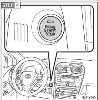
text_image
STEP 4 ENGINE START STOP IT21Y083Press the "ENGINE START STOP" switch.
The engine can be started from any "ENGINE START STOP" switch mode.
Continue depressing the clutch pedal until the engine is completely started. The engine will crank until it starts or for up to 30 seconds, whichever is less.
Diesel engine only: Indicator turns on. The engine begins starting after the indicator light goes out.
- Changing "ENGINE START STOP" switch mode
Modes can be changed by pressing the “ENGINE START STOP” switch with the brake pedal (vehicles with a Multidrive or automatic transmission) or clutch pedal (vehicles with a manual transmission) released. (The mode changes each time the switch is pressed.)

flowchart
graph LR
    A["Engine Start Stop"] --> B["Start Stop"]
    B --> C["Start Stop"]
    C --> D["End"]
1 OFF\*
Emergency flashers can be used.
2 ACCESSORY mode
Some electrical components such as the audio system can be used.
The "ENGINE START STOP" switch indicator turns amber.
3 IGNITION ON mode
All electrical components can be used.
The "ENGINE START STOP" switch indicator turns amber.
*: For vehicles with a Multidrive or automatic transmission, if the shift lever is in a position other than "P" when turning off the engine, the "ENGINE START STOP" switch will be turned to ACCESSORY mode, not to OFF.
■ If the engine does not start
The engine immobilizer system may not have been deactivated. ( P. 135)
■ When the steering lock cannot be released
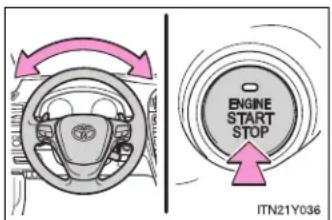
text_image
ENGINE START STOP ITN21Y036The green indicator light on the "ENGINE START STOP" switch will flash. To free it, press the "ENGINE START STOP" switch while turning the steering wheel slightly in either direction.
- When the “ENGINE START STOP” switch indicator flashes in amber
The system may be malfunctioning. Have the vehicle inspected by any authorized Toyota dealer or repairer, or another duly qualified and equipped professional, immediately.
■ Auto power off function
▶ Vehicles with a Multidrive or automatic transmission
If the vehicle is left in ACCESSORY mode for more than an hour with the shift lever in "P", the "ENGINE START STOP" switch will automatically turn OFF.
▶ Vehicles with a manual transmission
If the vehicle is left in ACCESSORY mode for more than an hour, the "ENGINE START STOP" switch will automatically turn OFF.
Electronic key battery depletion
→P. 46
■ When the electronic key battery is discharged
→P. 702
2-1. Driving procedures
■ Conditions affecting operation
→P. 44
Note for the smart entry & start system
→P. 47

CAUTION
■ When starting the engine
Always start the engine while sitting in the driver's seat. Do not depress the accelerator while starting the engine under any circumstances.
Doing so may cause an accident resulting in death or serious injury.
■ Stopping the engine in an emergency
If you want to stop the engine in an emergency while driving the vehicle, press and hold the "ENGINE START STOP" switch for more than 3 seconds, or press it briefly 3 times or more in succession.
However, do not touch the “ENGINE START STOP” switch while driving except in an emergency. Turning the engine off while driving will not cause loss of steering or braking control, but the power assist to these systems will be lost. This will make it more difficult to steer and brake, so you should pull over and stop the vehicle as soon as it is safe to do so.

NOTICE
■ To prevent battery discharge
Do not leave the "ENGINE START STOP" switch in ACCESSORY or IGNITION ON mode for long periods without the engine running.
■ When starting the engine
- Do not race a cold engine.
- If the engine becomes difficult to start or stalls frequently, have the engine checked immediately.
2-1. Driving procedures
Engine (ignition) switch (vehicles without smart entry & start system)
■ Starting the engine
▶ Multidrive
STEP 1 Check that the parking brake is set.
STEP 2 Check that the shift lever is set in "P".
STEP 3 Sit in the driver's seat and firmly depress the brake pedal.
STEP 4 Turn the engine switch to the "START" position and start the engine.
▶ Automatic transmission (diesel engine)
STEP 1 Check that the parking brake is set.
STEP 2 Check that the shift lever is set in "P".
STEP 3 Sit in the driver's seat and firmly depress the brake pedal.
STEP 4 Turn the engine switch to the "ON" position.
∞ indicator light turns on.
STEP 5 After indicator light goes out, turn the engine switch to the "START" position and start the engine.
▶ Manual transmission (gasoline engine)
STEP 1 Check that the parking brake is set.
STEP 2 Check that the shift lever is set in "N".
STEP 3 Sit in the driver's seat and firmly depress the clutch pedal.
STEP 4 Turn the engine switch to the "START" position and start the engine.
2-1. Driving procedures
▶ Manual transmission (diesel engine)
STEP 1 Check that the parking brake is set.
STEP 2 Check that the shift lever is set in "N".
STEP 3 Sit in the driver's seat and firmly depress the clutch pedal.
STEP 4 Turn the engine switch to the "ON" position.
∞ indicator light turns on.
STEP 5 After indicator light goes out, turn the engine switch to the "START" position and start the engine.
■ Engine (ignition) switch
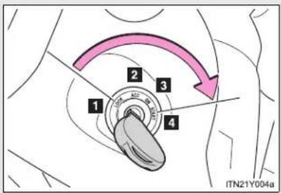
text_image
1 2 3 4 ITN21Y004a1 "LOCK"
The steering wheel is locked and the key can be removed. (Vehicles with a Multidrive or automatic transmission: The key can be removed only when the shift lever is in "P".)
2 "ACC"
Some electrical components such as the audio system can be used.
3 "ON"
All electrical components can be used.
4 "START"
For starting the engine.
■ When the steering lock cannot be released
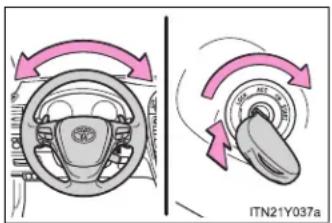
text_image
ITN21Y037aWhen starting the engine, the engine switch may seem stuck in the "LOCK" position. To free it, turn the key while turning the steering wheel slightly in either direction.
■ If the engine does not start
The engine immobilizer system may not have been deactivated. (→P. 135)
■ Key reminder function
A buzzer sounds if the driver's door is opened, while the key is in the engine switch to remind you to remove the key.

CAUTION
■ When starting the engine
Always start the engine while sitting in the driver's seat. Do not press the accelerator pedal while starting the engine under any circumstances. Doing so may cause an accident resulting in death or serious injury.
■ While driving
Do not turn the engine switch to the "LOCK" position. If in an emergency, you must turn the engine off while the vehicle is moving, turn the engine switch only to the "ACC" position.
2-1. Driving procedures

NOTICE
■ To prevent battery discharge
Do not leave the engine switch in the "ACC" or "ON" position for long periods if the engine is not running.
■ When starting the engine
- Do not crank for more than 30 seconds at a time. This may overheat the starter and wiring systems.
Do not race the cold engine. - If the engine becomes difficult to start or stalls frequently, have the engine checked immediately.
2-1. Driving procedures
Multidrive
Select a shift position appropriate for the driving conditions.
■ Shifting the shift lever

text_image
P R N M-D - IT121Y073
Vehicles with smart entry & start system:
While the "ENGINE START STOP" switch is in IGNITION ON mode, depress the brake pedal and move the shift lever. Vehicles without smart entry & start system:
While the engine switch is in the "ON" position, depress the brake pedal and move the shift lever.
2-1. Driving procedures
■ Selecting a shift position
| Shift position Function | |
| P Parking the vehicle or starting the engine | |
| R Reversing | |
| N Neutral | |
| D | Normal driving*1or temporary gear step selection driving*2 |
| M | 7-speed sport sequential shiftmatic mode driving (→P. 222) |
*1: To improve fuel consumption and reduce noises, set the shift lever in the "D" position for normal driving.
*2: If equipped, by selecting gear step using paddle shift switches, you can control engine braking forces.
- Selecting a driving mode
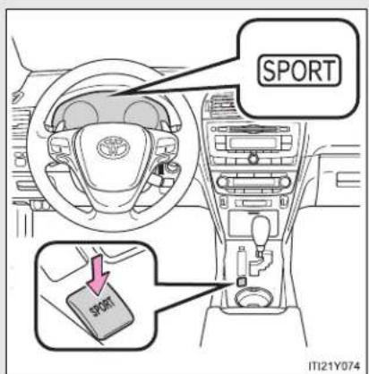
text_image
SPORT SPORT IT121Y074Press the switch.
For powerful acceleration and driving in mountainous regions.
Press the switch once more to return the normal mode.
Driving in the "D" position
Shift lever
If the shift lever is shifted into the "D" position, the most appropriate gear ratio is automatically selected, as determined by the driving conditions.
- Paddle shift switches (if equipped)
While the shift lever is in the "D" position, engine braking force can be temporarily switched to.

text_image
D → D 3 2 1 M21Y0751 Upshifting
2 Downshifting
Unless the paddle shift switches are operated, the gear step displayed on the meter cluster is fixed.
However, even when in the "D" position, the gear steps will be automatically changed if the engine speed is too high, or too low.
2-1. Driving procedures
Driving in the "M" position
By shifting the shift lever into the "M" position, 7 stages of gear step can be switched between.
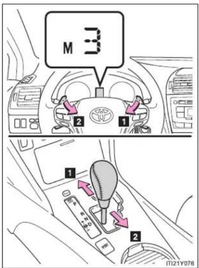
text_image
M 3 2 1 1 2 11121Y0761 Upshifting
2 Downshifting
Unless the shift lever or paddle shift switches (if equipped) are operated, the gear step displayed on the meter cluster is fixed.
However, even when in the "M" position, the gear steps will be automatically changed if the engine speed is too high, or too low.
■ Paddle shift switch (if equipped)
- When the paddle shift switch is operated in the "D" position, a gear step will be automatically selected according to the vehicle speed and driving conditions.
-
Automatic deactivation of gear step selection in the "D" position Gear step selection in the "D" position will be deactivated in the following situations:
-
The “+” paddle shift switch is held down for a period of time
- When the vehicle comes to a stop
- If the accelerator pedal is depressed for longer than a certain period of time in one shift range
■ Downshifting restrictions warning buzzer
To help ensure safety and driving performance, downshifting operation may sometimes be restricted. In some circumstances, downshifting may not be possible even when the shift lever or paddle shift switches (if equipped) is operated. (The warning buzzer will sound twice.)
■ When driving with cruise control activated
Even when performing the following actions with the intent of enabling engine braking, engine braking will not activate because cruise control will not be canceled.
- While driving “D” or “M” mode, downshifting to “6”, “5” or “4”. (→P. 275)
- When switching the driving mode to sport mode while driving in "D" position. (→P. 220)
2-1. Driving procedures
■ Automatic deactivation of sport mode
▶ Vehicles with smart entry & start system
If the "ENGINE START STOP" switch is turned OFF after driving in sport mode, the mode is automatically deactivated.
▶ Vehicles without smart entry & start system
If the engine switch is turned to the "LOCK" position after driving in sport mode, the mode is automatically deactivated.
If the shift lever cannot be shifted from "P"
→P. 692
If the "M" indicator is not displayed after shifting the shift lever to the "M" position
If the display does not change to "M" on an occasion other than that described above, it may indicate a malfunction in the transmission system. Have your vehicle inspected by any authorized Toyota dealer or repairer, or another duly qualified and equipped professional immediately.
■ Automatic gear step selection
When the vehicle comes to a stop, the transmission will automatically downshift to allow you to start off in 1st step.
2-1. Driving procedures
Automatic transmission
Select a shift position appropriate for the driving conditions.
■ Shifting the shift lever

text_image
P R N M-D IT21Y073
Vehicles with smart entry & start system:
While the "ENGINE START STOP" switch is in IGNITION ON mode, depress the brake pedal and move the shift lever. Vehicles without smart entry & start system:
While the engine switch is in the "ON" position, depress the brake pedal and move the shift lever.
2-1. Driving procedures
■ Selecting a shift position
| Shift position Function | |
| P Parking the vehicle or starting the engine | |
| R Reversing | |
| N Neutral | |
| D | Normal driving*1or temporary shift range selection driving*2 |
| M “M” mode driving (→P. 228) | |
*1: To improve fuel consumption and reduce noises, set the shift lever in the "D" position for normal driving.
*2: If equipped, by selecting shift ranges using paddle shift switches, you can control engine braking forces.
■ Selecting a driving mode
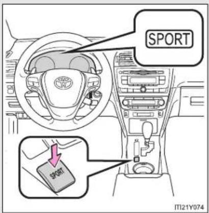
text_image
SPORT SPORT IT121Y974Press the switch.
For powerful acceleration and driving in mountainous regions.
Press the switch once more to return the normal mode.
Driving in the "D" position
Shift lever
If the shift lever is shifted into the "D" position, the most appropriate gear is automatically selected, as determined by the driving conditions.
- Paddle shift switches (if equipped)
While the shift lever is in the "D" position, engine braking force can be temporarily switched to.
By firstly operating the “-” paddle shift switch, the “-” and “+” switches can be used to freely switch the shift range.
Changing the shift range allows restriction of the highest gear, preventing unnecessary upshifting and enabling the level of engine braking force to be selected.

text_image
Range Display 1 2 3 4 5 6 6 5 4 3 2 1 ITN21Y0251 Higher shift range
2 Lower shift range
The gear is automatically shifted up or down between 1 and the selected shift range (displayed on the meter cluster).
2-1. Driving procedures
Driving in the "M" position
By shifting the shift lever into the "M" position, 6 stages of gear can be switched between.

text_image
M 3 2 1 1 2 11121Y0761 Upshifting
2 Downshifting
Unless the shift lever or paddle shift switches (if equipped) are operated, the gear displayed on the meter cluster is fixed.
However, even when in the "M" position, the gear will be automatically changed in the following situations:
- When the vehicle speed drops (downshift only)
- When the automatic transmission fluid temperature is extremely high (upshift only)
■ Paddle shift switch (if equipped)
- When the “-” paddle shift switch is operated in the “D” position, a shift range will be automatically selected. The highest gear of the first shift range will be one gear lower than the gear in use during normal “D” position driving.
-
Automatic deactivation of shift range selection in the "D" position Shift range selection in the "D" position will be deactivated in the following situations:
-
The “+” paddle shift switch is held down for a period of time
- When the vehicle comes to a stop
- If the accelerator pedal is depressed for longer than a certain period of time in one shift range
■ Downshifting restrictions warning buzzer
To help ensure safety and driving performance, downshifting operation may sometimes be restricted. In some circumstances, downshifting may not be possible even when the shift lever or paddle shift switches (if equipped) is operated. (The warning buzzer will sound twice.)
■ When driving with cruise control or radar cruise control activated
Even when performing the following actions with the intent of enabling engine braking, engine braking will not activate because cruise control or radar cruise control will not be canceled.
● While driving “D” mode, downshifting to “5” or “4”. (→P. 275, 281)
- When switching the driving mode to sport mode while driving in "D" position. (→P. 226)
2-1. Driving procedures
■ Automatic deactivation of sport mode
▶ Vehicles with smart entry & start system
If the "ENGINE START STOP" switch is turned OFF after driving in sport mode, the mode is automatically deactivated.
▶ Vehicles without smart entry & start system
If the engine switch is turned to the "LOCK" position after driving in sport mode, the mode is automatically deactivated.
If the shift lever cannot be shifted from "P"
→P. 692
If the "M" indicator is not displayed after shifting the shift lever to the "M" position
- Vehicles with smart entry & start system: Within a few seconds of turning the "ENGINE START STOP" switch to IGNITION ON mode, the transmission will not go into "M" mode if the shift lever is moved to the "M" position.
Vehicles without smart entry & start system: Within a few seconds of turning the engine switch to the "ON" position, the transmission will not go into "M" mode if the shift lever is moved to the "M" position.
This is because a system check is being performed. In this case, wait a moment and then try moving the shift lever to the "M" position again.
- If the display does not change to "M" on an occasion other than that described above, it may indicate a malfunction in the transmission system. Have your vehicle inspected by any authorized Toyota dealer or repairer, or another duly qualified and equipped professional immediately.
■ Automatic gear selection
When the vehicle comes to a stop, the transmission will automatically downshift to allow you to start off in 1st gear.
If the automatic transmission temperature warning message is displayed
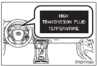
text_image
HIGH TRANSMISSION FLUID TEMPERATURE ITN21Y050If the automatic transmission fluid temperature warning message is displayed while driving, make sure you return to normal "D" position driving and reduce speed by easing off the accelerator pedal. Stop the vehicle in a safe place, shift the shift lever to the "P" position and let the engine idle until the warning message is extinguished.
When the warning message is no longer shown, the vehicle can be driven again.
If the warning message is not extinguished even after a short time, have your vehicle inspected by any authorized Toyota dealer or repairer, or another duly qualified and equipped professional.
AI-SHIFT
The AI-SHIFT automatically shifts the gear to the suitable position according to the driver performance and driving conditions.
The AI-SHIFT automatically operates when the shift lever is in the "D" position. (Shifting the shift lever to the "M" position cancels the function.)
2-1. Driving procedures
Manual transmission
■ Shifting the shift lever
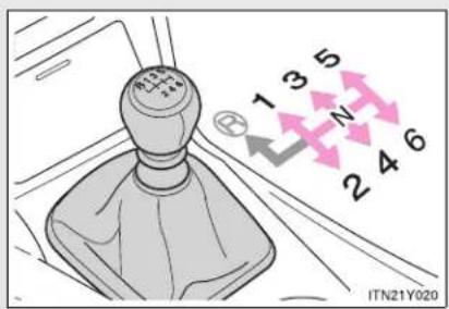
text_image
1 3 5 N 2 4 6 ITN21Y020Fully depress the clutch pedal before operating the shift lever, and then release it slowly.
■ Shifting the shift lever to "R"
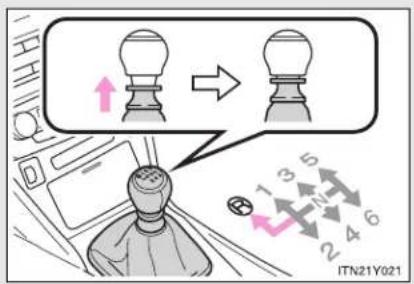
text_image
ITN21Y021Shift the shift lever to the "R" position while lifting up the ring section.
Gear Shift Indicator (if equipped)
The Gear Shift Indicator display is a guide to help the driver achieve improved fuel economy and reduced exhaust emissions within limits of engine performance.
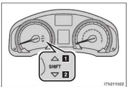
text_image
1 SHIFT 2 ITN21Y0221 Upshifting
2 Downshifting
Gear Shift Indicator display
The Gear Shift Indicator may not be displayed when your foot is placed on the clutch pedal.
2-1. Driving procedures
■ Maximum allowable speeds
Observe the following maximum allowable speeds in each gear when maximum acceleration is necessary.
▶ Gasoline engine
km/h (mph)
| Shift position | Maximum speed | ||
| 1ZR-FAE engine | 2ZR-FAE engine | 3ZR-FAE engine | |
| 1 49 (30) | 52 (32) 53 (33) | ||
| 2 90 (56) | 95 (59) 91 (57) | ||
| 3 131 (81) | 139 (86) 136 (85) | ||
| 4 177 (110) | 188 (117) 183 (114) | ||
| 5 195 (121) | 200 (124) 200 (124) | ||
▶ Diesel engine
km/h (mph)
| Shift position | Maximum speed | ||
| 1AD-FTV engine | 2AD-FTV engine | 2AD-FHV engine | |
| 1 37 (23) | 40 (25) 37 (23) | ||
| 2 73 (45) | 73 (45) 68 (42) | ||
| 3 115 (71) | 115 (71) 107 (67) | ||
| 4 164 (102) | 159 (99) 149 (92) | ||
| 5 190 (118) | 200 (124) 190 (118) | ||

CAUTION
Gear Shift Indicator display
Refer to the display while considering actual traffic and road conditions. Failure to exercise judgment may lead to an accident.

NOTICE
■ To prevent damage to the transmission

text_image
R 1 3 5 ← 2 4 6 IT21Y078- Do not shift the shift lever to "R" without depressing the clutch pedal.
Do not lift up the ring section except when shifting the lever to "R".
Shift the shift lever to "R" only when the vehicle is stationary.
2-1. Driving procedures
Turn signal lever

text_image
Diagram showing car intake and exhaust behavior with directional arrows indicating movement or flow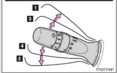
text_image
1 3 4 2 ITN21Y0411 Right turn
2 Left turn
3 Move and hold the lever partway to signal a lane change.
The right hand signal will flash until you release the lever.
4 Move and hold the lever partway to signal a lane change.
The left hand signal will flash until you release the lever.
■ Turn signals can be operated when
▶ Vehicles with smart entry & start system
The "ENGINE START STOP" switch is in IGNITION ON mode.
▶ Vehicles without smart entry & start system
The engine switch is in the "ON" position.
If the indicators flash faster than usual
Check that a light bulb in the front or rear turn signal lights has not burned out.
2-1. Driving procedures
Parking brake
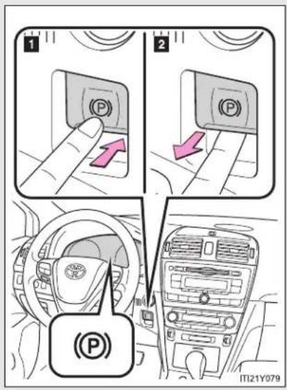
text_image
1 2 (P) (P) (P) ITI21Y0791 Press the switch to set
The parking brake indicator light will flash, and the light will remain on when the parking brake is applied.
Press and hold the parking brake switch if an emergency occurs and it is necessary to operate the parking brake while driving.
2 Pull the switch to release
Parking brake operation
▶ Vehicles with smart entry & start system
When the "ENGINE START STOP" switch is not in IGNITION ON mode, the parking brake cannot be released using the parking brake switch.
▶ Vehicles without smart entry & start system
When the engine switch is not in the "ON" position, the parking brake cannot be released using the parking brake switch.
■ Automatic release function (vehicles with a manual transmission)
When starting, if the shift lever is engaged, the accelerator pedal and clutch pedal are operated while the parking brake is applied, the parking brake will be automatically released, thus making starting off easier.
2-1. Driving procedures
■ Automatic apply function (vehicles with a manual transmission)
- To prevent the parking brake from being left accidentally unapplied, the parking brake will be applied automatically under the following conditions when the "ENGINE START STOP" switch is switched to ACCESSORY mode (vehicles with smart entry & start system), or the engine switch is switched to the "ACC" position (vehicles without smart entry & start system):
• Automatic apply mode is ON
• The vehicle is stopped
- Switching automatic apply mode
Automatic apply mode is initially set to ON, but it can be switched between ON and OFF as the situation demands.
STEP 1 Stop the vehicle in a horizontal condition and switch the "ENGINE START STOP" switch to IGNITION ON mode (vehicles with smart entry & start system), or switch the engine switch to the "ON" position (vehicles without smart entry and start system)

text_image
STEP 2 P AUTQ ITI21Y081aWhen switching automatic apply mode from ON to OFF:
Pull and hold the parking brake switch for 5 seconds or more
The Auto P-off indicator light will illuminate.
When switching automatic apply mode from OFF to ON:
Push and hold the parking brake switch for 5 seconds or more
The Auto P-off indicator light will go off.
- Temporary cancelation of the automatic apply function is available for specific circumstances (car wash, towing vehicle, etc.).
To activate temporary cancelation, parking brake switch need to be pulled when "ENGINE START STOP" switch is switched to ACCESSORY mode (vehicles with smart entry & start system), or the engine switch is switched to the "ACC" position (vehicles without smart entry & start system).
When switch is being pulled for 5 seconds or more, automatic apply mode changes from ON to OFF.
- Parking brake operation sound
When the parking brake operates, a motor sound (whirring sound) may be heard. This does not indicate a malfunction.
■ When the system is overheating
The system may become temporarily unavailable in order to prevent overheating caused by repeated unnecessary switch operation. In this event, leaving the system to cool down for a short time will allow normal operation to resume.
■ When there is a malfunction in the system
Warning light will turn on or flash. (→P. 617)
■ Usage in winter time
→P. 344

CAUTION
■ When leaving the vehicle
Make sure that the parking brake indicator light is illuminated. If the parking brake is not applied, the vehicle could move, possibly leading to an accident.
2-1. Driving procedures

NOTICE
■ When parking the vehicle
Before you leave the vehicle, set the parking brake, shift the shift lever to "P" (Multidrive or automatic transmission) or "1" or "R" (manual transmission) and make sure that the vehicle does not move.
■ When the parking brake cannot be released due to a malfunction
Use the parking brake release tool to manually release the parking brake. (→P. 693)
Driving the vehicle with the parking brake set will lead to brake components overheating, which may affect braking performance and increase brake wear.
2-1. Driving procedures
Horn
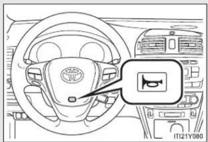
text_image
Diagram of a car dashboard with a traffic light indicator and a logo on the steering wheelTo sound the horn, press on or close to the mark.
■ After adjusting the steering wheel (vehicles with manual tilt and telescopic steering)
Make sure that the steering wheel is securely locked.
The horn may not sound if the steering wheel is not securely locked.
2-2. Instrument cluster
Gauges and meters

text_image
1 2 3 4 000 100km H 1/1 C R 28:88 6 7 8 9 5 ITN21Y014▶ Vehicles with smart entry & start system
The following gauges, meters and displays illuminate when the "ENGINE START STOP" switch is in IGNITION ON mode.
▶ Vehicles without smart entry & start system
The following gauges, meters and displays illuminate when the engine switch is in the "ON" position.
1 Tachometer
Displays the engine speed in revolutions per minute.
2 Multi-information display
Presents the driver with a variety of driving related data. (→P. 249)
3 Odometer and trip meter
▶ Odometer
Displays the total distance the vehicle has been driven.
▶ Trip meter
Displays the distance the vehicle has been driven since the meter was last reset. Trip meters A and B can be used to record and display different distances independently.
4 Speedometer
Displays the vehicle speed.
5 "DISP."/instrument panel light control button
Press: Switches the multi-information display.
Turn: To adjust the brightness of the instrument panel light. (→P. 244)
6 Fuel gauge
Displays the quantity of fuel remaining in the tank.
7 Clock
Displays the time.
8 Engine coolant temperature gauge
Displays the engine coolant temperature.
9 Odometer/trip meter and trip meter reset button
Switches between odometer and trip meter displays. Pushing and holding the button will reset the trip meter when the trip meter is being displayed.
Instrument panel light control
The brightness of the instrument panel light can be adjusted when the headlight switch is on.
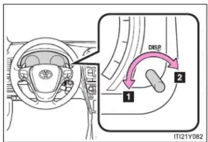
text_image
DISP 1 2 ITI21Y0821 Darker
2 Brighter
Tail cancel feature
When turning the instrument panel light control button all the way clockwise (brighter), the brightness will become suddenly very bright.
Use this feature when driving during daytime with your headlights on, it will improve visibility of the instrument panel.
NOTICE
■ To prevent damage to the engine and its components
- Do not let the indicator needle of the tachometer enter the red zone, which indicates the maximum engine speed.
The engine may be overheating if the engine coolant temperature gauge is in the red zone ("H"). In this case, immediately stop the vehicle in a safe place, and check the engine after it has cooled completely. (→P. 710)
2-2. Instrument cluster
Indicators and warning lights
The indicator and warning lights on the instrument cluster and center panel inform the driver of the status of the vehicle's various systems.
For the purpose of explanation, the following illustration displays all indicators and warning lights illuminated.
▶ Instrument cluster

text_image
Technical diagram of a car dashboard with dual gauges, display, and control buttons labeled in Chinese.The units used on the speedometer, tachometer and some indicators may differ depending on the engine, transmission, etc.
▶ Center panel
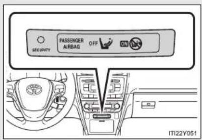
text_image
SECURITY PASSenger AIRBAG OFF IT122Y051Indicators
The indicators inform the driver of the operating state of the vehicle's various systems.

Turn signal indicator ( P. 236)

Cruise control indicator ( P. 275)

Headlight high beam indicator ( P. 263)

"SET" indicator ( P. 275, 281)

Tail light indicator ( P. 262)

Speed limiter indicator ( P. 300)

Front fog light indicator ( P. 267)

Dynamic radar cruise control indicator ( P. 281)

Rear fog light indicator ( P. 267)

"LKA" indicator (→P. 318)

Slip indicator ( P. 328)
"AFS OFF" indicator (→P. 263)

Engine preheating indicator ( P. 210, 215)

Eco Driving Indicator Light ( P. 198)

Security indicator ( P. 135, 146)
Auto P-off indicator ( P. 238)
(If equipped)
Shift position indicator (→P. 222, 228)

(If equipped)
"SPORT" indicator (→P. 220, 226)

(If equipped)
Gear Shift Indicator (→P. 233)

Parking brake indicator ( P. 237)

(If equipped)
"PCS" warning (→P. 333)
"PASSENGER AIRBAG" indicator (→P. 190)
Warning lights
Warning lights inform the driver of malfunctions in any of the vehicle's systems. (→P. 617)

text_image
*1 *1 *1 *1 *1 *1 *1 *1 *(Red) (Yellow) (ABS) PCS (If equipped)
text_image
*1 *1, 6 *6 *6 *6 *6 *1 AFS OFF (LKA) (If equipped) (If equipped) (If equipped) (If equipped) (If equipped)
2-2. Instrument cluster
*1: These lights turn on when the "ENGINE START STOP" switch is turned to IGNITION ON mode (vehicles with smart entry & start system) or the engine switch is turned to the "ON" position (vehicles without smart entry & start system) to indicate that a system check is being performed. They will turn off after the engine is started, or after a few seconds. There may be a malfunction in a system if a light does not turn on, or if the lights do not turn off. Have the vehicle inspected by any authorized Toyota dealer or repairer, or another duly qualified and equipped professional for details.
*2: The light flashes quickly to indicate that the system is operating.
^*3 : The light turns on when the system is turned off.
*4: Vehicles with a Multidrive or automatic transmission
*5: Vehicles with a manual transmission
*6: The light flashes to indicate a malfunction.

CAUTION
If a safety system warning light does not come on
Should a safety system light such as ABS and the SRS airbag warning light not come on when you start the engine, this could mean that these systems are not available to help protect you in an accident, which could result in death or serious injury. Have the vehicle inspected by any authorized Toyota dealer or repairer, or another duly qualified and equipped professional immediately if this occurs.
2-2. Instrument cluster
Multi-information display
The multi-information display presents the driver with a variety of driving-related data.
text_image
000 123456km ITI22Y052- Trip information (→P. 251)
Displays driving range, fuel consumption and other cruising-related information.
- Date (→P. 251)
Indicates the date and sets it.
● Outside temperature display ( P. 251)
Indicates the outside temperature.
- Warning messages
$$ (\rightarrow \mathrm{P}. 6 2 4) $$
Automatically displayed when a malfunction occurs in one of the vehicle's systems.
2-2. Instrument cluster
Switch the display
▶ "DISP." button

text_image
IT122Y053Display items can be switched by pressing the "DISP." button.
▶ "DISP" switch
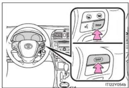
text_image
IT122Y054bVehicles with audio system including "touch screen": Display items can be switched by pressing the "DISP" switch.
Trip information
● Date and outside temperature display

text_image
THURSDAY 10/06/2010 20 °C ODO 100 km ITN22Y026Displays the date and outside temperature.
The temperature range that can be displayed is from -40^ ( -40^ ) to 50^ ( 122^ ).
- Instantaneous fuel consumption

text_image
CURRENT FUEL CONSUMPTION 0/100km 30 0DO 100km ITN22Y002Displays the instantaneous fuel consumption.
2-2. Instrument cluster
● Average fuel consumption
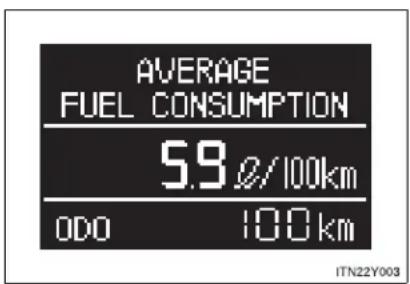
text_image
AVERAGE FUEL CONSUMPTION 5.9 Ø/100km ODO 100 km ITN22Y003Displays the average fuel consumption since the function was last reset.
- The function can be reset by pressing the "DISP." button or "DISP" switch for longer than 1 second when the average fuel consumption is displayed.
- Use the displayed average fuel consumption as a reference.
- Eco Driving Indicator Zone Display (if equipped)
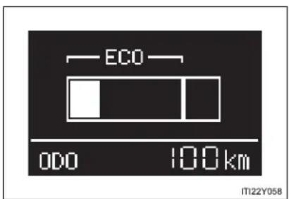
text_image
ECO ODO 100km IT122Y058The ratio of the current acceleration to the Zone of Eco driving is displayed.
- Driving range
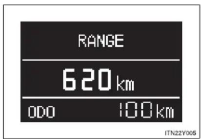
text_image
RANGE 620 km ODO 100 km ITN22Y005Displays the estimated maximum distance that can be driven with the quantity of fuel remaining.
- This distance is computed based on your average fuel consumption. As a result, the actual distance that can be driven may differ from that displayed.
- When only a small amount of fuel is added to the tank, the display may not be updated.
When refueling, turn the "ENGINE START STOP" switch off (vehicles with smart entry & start system) or the engine switch to the "LOCK" position (vehicles without smart entry & start system).
If the vehicle is refueled without turning the "ENGINE START STOP" switch off or the engine switch to the "LOCK" position, the display may not be updated.
2-2. Instrument cluster
● Average vehicle speed

text_image
AVERAGE SPEED 38 km/h ODO 100 km ITN22Y006Displays the average vehicle speed since the function was last reset.
The function can be reset by pressing the "DISP." button or "DISP" switch for longer than 1 second when the average vehicle speed is displayed.
- Elapsed time
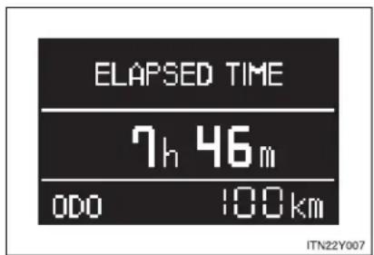
text_image
ELAPSED TIME 7h 46m 000 100km ITN22Y007Displays the elapsed time since the function was last reset.
The function can be reset by pressing the "DISP." button or "DISP" switch for longer than 1 second when the elapsed time is displayed.
● Rear passengers seat belt reminder display

text_image
000 100km ITN22Y008The seat belt status of the rear seat passenger is displayed.
White circles are displayed if seat belts are not being worn; they will disappear once the seat belt is applied.
Set up display
Before setting
STEP 1 Display the settings screen on the multi-information display when the vehicle is stopped.
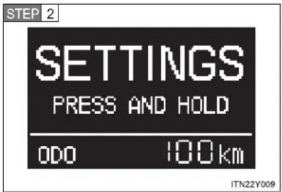
text_image
STEP 2 SETTINGS PRESS AND HOLD 0DO 100km ITN22Y009Press and hold the "DISP." button or "DISP" switch to enter the adjustment mode.
STEP 3 Select the desired item on the menu screen.
Press and hold the "DISP." button or "DISP" switch to enter the adjustment mode.

text_image
CLOCK CLOCK FORMAT DATE DATE FORMAT ODO 100km LANGUAGE ECO INDICATOR UNITS +BACK ODO 100km ITN22Y010Setting the clock
STEP 1 Select "CLOCK" on the menu screen.
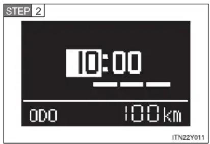
text_image
STEP 2 10:00 000 100km ITN22Y011Press the "DISP." button or "DISP" switch to adjust the hours.
After setting the hours, wait for 5 seconds until the bar disappears, and confirm that the hour has been input.
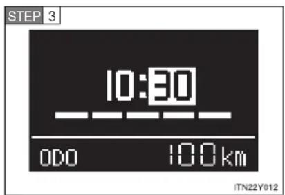
text_image
STEP 3 10:30 000 100km ITN22Y012Press the "DISP." button or "DISP" switch to adjust the minutes.
After setting the minutes, wait for 5 seconds until the bar disappears, and confirm that the minutes has been input.
■ Setting the clock format
STEP 1 Select "CLOCK FORMAT" on the menu screen.
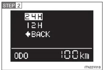
text_image
STEP 2 24H 12H +BACK 0DO 100km ITN22Y013Select the desired clock format.
Press and hold the "DISP." button or "DISP" switch to input the choice.
Setting the date
STEP 1 Select "DATE" on the menu screen.

text_image
STEP 2 23/01/2010 00:00 100km ITN22Y023Press the "DISP." button or "DISP" switch to adjust the year.
After setting the year, wait for 5 seconds until the bar disappears, and confirm that the year has been input.
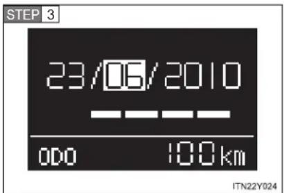
text_image
STEP 3 23/06/2010 00:00 100 km ITN22Y024Press the "DISP." button or "DISP" switch to adjust the month.
After setting the month, wait for 5 seconds until the bar disappears, and confirm that the month has been input.

text_image
STEP 4 10/06/2010 000 100 km ITN22Y025Press the "DISP." button or "DISP" switch to adjust the day.
After setting the day, wait for 5 seconds until the bar disappears, and confirm that the day has been input.
■ Setting the date format
STEP 1 Select "DATE FORMAT" on the menu screen.

text_image
STEP 2 DD,MM,YYYY MM,DD,YYYY YYYY,MM,DD +BACK 0DO 100km ITN22Y017Select the desired date format.
Press and hold the "DISP." button or "DISP" switch to input the choice.
■ Selecting the language
STEP 1 Select "LANGUAGE" on the menu screen.
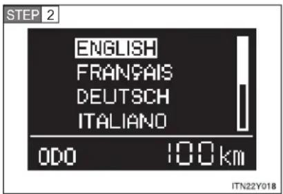
text_image
STEP 2 ENGLISH FRANÇAIS DEUTSCH ITALIANO ODO 100 km ITN22Y018Select the desired language.
Press and hold the "DISP." button or "DISP" switch to input the choice.
■ Setting Eco Driving Indicator Light
STEP 1 Select "ECO INDICATOR" on the menu screen.
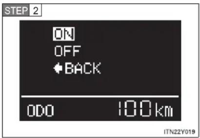
text_image
STEP 2 ON OFF +BACK ODO 100km ITN22Y019Select the desired setting.
Press and hold the "DISP." button or "DISP" switch to input the choice.
This setting does not turn Eco Driving Indicator Zone Display on/off.
- Selecting the units
STEP 1 Select "UNITS" on the menu screen.

text_image
STEP 2 km, Ø/100km km.km/Ø miles.mpg ←BACK ODO 100 km ITN22Y020Select the desired unit.
Press and hold the "DISP." button or "DISP" switch to input the choice.
■ Returning the previous screen
Select “←BACK” on the screen.
Press and hold the "DISP." button or "DISP" switch to input the choice.
■ Eco Driving Indicator Zone Display (if equipped)
The Eco-friendly acceleration operation (Eco-friendly driving) range is displayed along with the current amount of acceleration. If the accelerator pedal is depressed down too far and Zone of Eco driving is exceeded, the right-hand side of the bar-graph will begin to flash.
Also, it will not be operated if the following conditions are met while driving:
- The shift position is anything other than "D"
The vehicle is being driven in "SPORT" mode - If equipped, the paddle shift switch is operated while the shift position is "D"
● The vehicle speed is approximately 130 km/h (80 mph) or higher.
■ Rear seat belt reminder buzzer
The rear seat belts reminder sounds to alert the rear passenger that his/her seat belt is not fastened. The buzzer sounds for 30 seconds after the vehicle has reached a speed of at least 20 km/h (12 mph). Then, if the seat belt is still unfastened, the buzzer will sound in a different tone for 90 more seconds.
■ Outside temperature display
- In the following situations, the correct outside temperature may not be displayed, or the display may take longer than normal to change.
- When stopped, or driving at low speeds (less than 20 km/h [12 mph])
- When the outside temperature has changed suddenly (at the entrance/exit of a garage, tunnel, etc.)
- When “--” is displayed, the system may be malfunctioning.
Take your vehicle to any authorized Toyota dealer or repairer, or another duly qualified and equipped professional.
■ Customization that can be configured at any authorized Toyota dealer or repairer, or another duly qualified and equipped professional
Settings (on/off operation of Eco Driving Indicator Zone Display) can be changed. ( P. 752)
- Liquid crystal display
Small spots or light spots may appear on the display. This phenomenon is characteristic of liquid crystal displays, and there is no problem to continue using the display.

NOTICE
The multi-information display at low temperatures
Allow the interior of the vehicle to warm up before using the liquid crystal information display. At extremely low temperatures, the information display monitor may respond slowly, and display changes may be delayed.
2-3. Operating the lights and wipers
Headlight switch
The headlights can be operated manually or automatically.
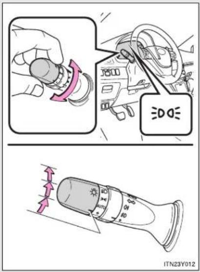
text_image
≡DOE ITN23Y012
The front position, tail, license plate and instrument panel lights turn on.

The headlights and all lights listed above turn on.
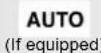
The headlights and all lights listed above turn on and off automatically.
(Vehicles with smart entry & start system: When the "ENGINE START STOP" switch is in IGNITION ON mode
Vehicles without smart entry & start system: When the engine switch is in the "ON" position)
Turning on the high beam headlights
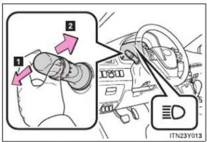
text_image
1 2 ITN23Y0131 With the headlights on, push the lever forward to turn on the high beams.
Pull the lever back to the center position to turn the high beams off.
2 Pull the lever toward you to turn on the high beams.
Release the lever to turn them off. You can flash the high beams with the headlights on or off.
AFS (vehicles with discharge headlights)
AFS (Adaptive Front-lighting System) improves visibility at intersections and or curves by automatically adjusting the level of the headlights according to vehicle speed and the degree of the tire angle that are controlled by steering input.
Operates at speed of 10 km/h (6 mph) or higher.
■ Deactivating AFS

text_image
AFS OFF AFS OFF ITN22Y022Press the switch to deactivate the AFS.
Manual headlight leveling dial (vehicles with halogen headlights)
The level of the headlights can be adjusted according to the number of passengers and the loading condition of the vehicle.

text_image
1 2 1 0 - D ITN23Y0111 Raises the level of the headlights
2 Lowers the level of the headlights
■ Guide to dial settings
| Occupancy and luggage load conditions | Dial position | |
| Occupants Luggage load | ||
| Driver None 0 | ||
| Driver and front passenger | None 0 | |
| All seats occupied None 1.5 | ||
| All seats occupied Full luggage loading 3 | ||
| Driver Full luggage loading 4 | ||
Daytime running light system
To make your vehicle more visible to other drivers, the daytime running lights turn on automatically (at a reduced intensity) whenever the engine is started and the parking brake is released. Daytime running lights are not designed for use at night.
■ Headlight control sensor (if equipped)
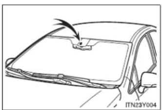
natural_image
Line drawing of a car front panel with a handle and a small object on top, no text or symbols presentThe sensor may not function properly if anything that blocks the sensor is affixed to the windshield.
Doing so interferes with the sensor detecting the level of ambient light and may cause the automatic headlight system to malfunction.
■ Automatic light off system
▶ Vehicles with smart entry & start system
- When the light switch is in the "AUTO" position, the headlight and all the lights turn off automatically if the "ENGINE START STOP" switch is turned to ACCESSORY mode or turned OFF and the driver's door is opened.
- When the light switch is in the OFF position, the headlights and front fog lights turn off automatically if the "ENGINE START STOP" switch is turned to ACCESSORY mode or turned OFF.
To turn the lights on again, turn to IGNITION ON mode, or turn the light switch OFF once and then back to the -on-position.
▶ Vehicles without smart entry & start system
- When the light switch is in the "AUTO" position, the headlight and all the lights turn off automatically if the engine switch is turned to the "ACC" or "LOCK" position and the driver's door is opened.
- When the light switch is in the "OFF" position, the headlights and front fog lights turn off automatically if the engine switch is turned to the "ACC" or "LOCK" position.
To turn the lights on again, turn to the "ON" position, or turn the light switch OFF once and then back to the -on-position.
2-3. Operating the lights and wipers
Light reminder buzzer
▶ Vehicles with smart entry & start system
A buzzer sounds when the "ENGINE START STOP" switch is turned OFF or to ACCESSORY mode and the driver's door is opened while the lights are turned on.
▶ Vehicles without smart entry & start system
A buzzer sounds when the engine switch is turned to the "LOCK" or "ACC" position and the driver's door is opened while the lights are turned on.
■ Automatic headlight leveling system (vehicles with discharge headlights)
The level of the headlights is automatically adjusted according to the number of passengers and the loading condition of the vehicle to ensure that the headlights do not interfere with other road users.
If the AFS indicator flashes...
It may indicate a malfunction in the system. Contact any authorized Toyota dealer or repairer, or another duly qualified and equipped professional.
■ Customization that can be configured at any authorized Toyota dealer or repairer, or another duly qualified and equipped professional
Settings of the light sensor sensitivity can be changed.
(Customizable features → P. 751)

NOTICE
■ To prevent battery discharge
Do not leave the lights on longer than necessary when the engine is not running.
2-3. Operating the lights and wipers
Fog light switch
The fog lights secure excellent visibility in difficult driving conditions, such as in rain or fog.
▶ Vehicles with front fog lights
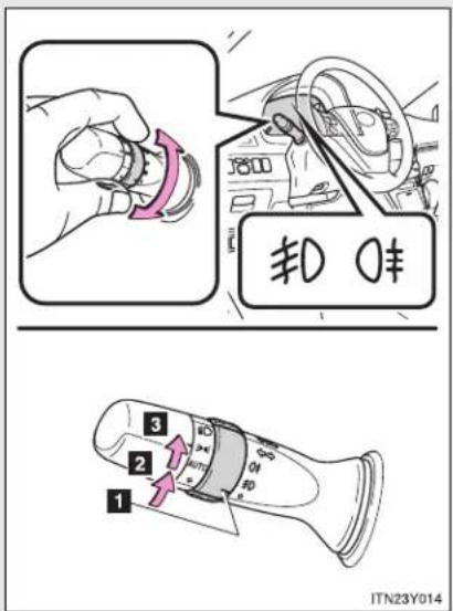
text_image
1 2 3 4 5 6 7 8 9 10 11 12 13 14 15 16 17 18 19 20 21 22 23 24 25 26 27 28 29 30 31 32 33 34 35 36 37 38 39 40 41 42 43 44 45 46 47 48 49 50 51 52 53 54 55 56 57 58 59 60 61 62 63 64 65 66 67 68 69 70 71 72 73 74 75 76 77 78 79 80 81 82 83 84 85 86 87 88 89 90 91 92 93 94 95 96 97 98 99 1001 Off
2 Front fog lights on
3 Both front and rear fog lights on (Rotating the switch ring again turns only the rear fog light off.)
Releasing the switch returns the ring to the position.
After the headlight switch is turned off, the rear fog lights do not come on even if you turn on the headlight switch again.
2-3. Operating the lights and wipers
▶ Vehicles without front fog lights

text_image
0¢ 1 2 ITN23Y0151 Off
2 Rear fog light on
■ Fog lights can be used when
▶ Vehicles with front fog lights
Front fog lights: The headlights or front position lights are turned on.
Rear fog lights: The front fog lights are turned on.
▶ Vehicles without front fog lights
The headlights or front position lights are turned on.
2-3. Operating the lights and wipers
Windshield wipers and washer
- Intermittent wiper with interval adjuster
Wiper intervals can be adjusted for intermittent operation (when

is selected).
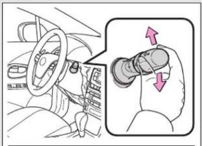
natural_image
Interior view of a car showing steering wheel and hand gesture (no text or symbols)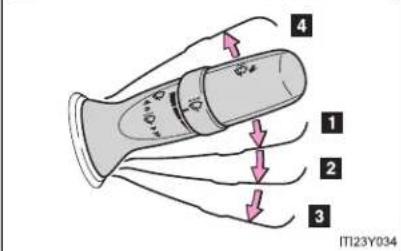
text_image
4 1 2 3 IT123Y034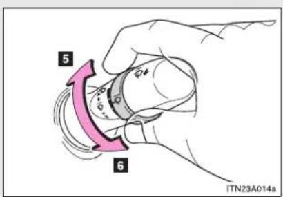
text_image
5 6 ITN23A014a1 Intermittent wiper operation
2 Low speed wiper operation
3 High speed wiper operation
4 Temporary operation
5 Increases the intermittent wiper frequency
6 Decreases the intermittent wiper frequency
2-3. Operating the lights and wipers
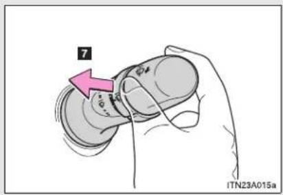
text_image
7 ITN23A015a7 Washer/wiper dual operation
Wipers operate automatically.
If the headlights are on, the headlight cleaners will operate once. And then, the headlight cleaners will operate every five times you pull the lever. (if equipped)
■ Rain-sensing windshield wipers
With "AUTO" selected, the wipers will operate automatically when the sensor detects falling rain. The system automatically adjusts wiper timing in accordance with rain volume.
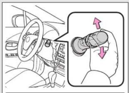
natural_image
Diagram showing a car interior with steering wheel and hand valve, plus a magnified inset highlighting the lever mechanism (no text or symbols present)1 Rain-sensing wiper operation
2 Low speed wiper operation
3 High speed wiper operation
4 Temporary operation
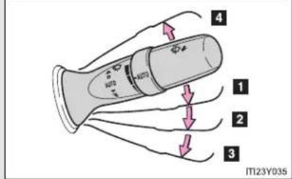
text_image
4 1 2 3 ITI23Y035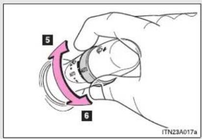
text_image
5 6 ITN23A017a5 Sensor sensitivity (high)
6 Sensor sensitivity (low)
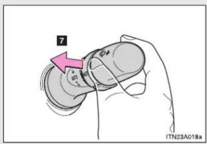
text_image
7 ITN23A018a7 Washer/wiper dual operation
Wipers operate automatically.
If the headlights are on, the headlight cleaners will operate once. And then, the headlight cleaners will operate every five times you pull the lever. (if equipped)
The windshield wiper and washer can be operated when
▶ Vehicles with smart entry & start system
The "ENGINE START STOP" switch is in IGNITION ON mode.
▶ Vehicles without smart entry & start system
The engine switch is in the "ON" position.
2-3. Operating the lights and wipers
■ Rain drop sensor (vehicles with rain-sensing windshield wipers)

natural_image
Technical line drawing of a car interior panel with a handle and mounting bracket (no text or symbols)The raindrop sensor judges the amount of raindrops.
▶ Vehicles with smart entry & start system
If the wiper switch is turned to the "AUTO" position while the "ENGINE START STOP" switch is in IGNITION ON mode, the wiper will operate once to show that "AUTO" mode is activated.
If the wiper sensitivity is adjusted to higher, the wiper may operate once to indicate the change of sensitivity.
▶ Vehicles without smart entry & start system
If the wiper switch is turned to the "AUTO" position while the engine switch is in the "ON" position, the wiper will operate once to show that "AUTO" mode is activated.
If the wiper sensitivity is adjusted to higher, the wiper may operate once to indicate the change of sensitivity.
If no windshield washer fluid sprays
Check that the washer nozzles are not blocked and if there is washer fluid in the windshield washer fluid reservoir.
■ Windshield wiper features
The rear window and outside rear view mirror defoggers automatically turn on when you operate the wipers.

CAUTION
■ Caution regarding the use of windshield wipers in "AUTO" mode
The windshield wipers may operate unexpectedly if the sensor is touched or the windshield is subject to vibration in "AUTO" mode. Take care that your fingers or anything else do not become caught in the windshield wipers.

NOTICE
■ When the windshield is dry
Do not use the wipers, as they may damage the windshield.
When there is no washer fluid spray from the nozzle
Damage to the washer fluid pump may be caused if the lever is pulled toward you and held continually.
When a nozzle becomes blocked
Do not try to clean it with a pin or other object. The nozzle will be damaged.
2-3. Operating the lights and wipers
Rear window wiper and washer (wagon)

text_image
IT123Y0361 Intermittent window wiper operation
2 Normal window wiper operation
3 Washer/wiper dual operation
4 Washer/wiper dual operation
The rear window wiper and washer can be operated when
▶ Vehicles with smart entry & start system
The "ENGINE START STOP" switch is in IGNITION ON mode.
▶ Vehicles without smart entry & start system
The engine switch is in the "ON" position.
NOTICE
When the rear window is dry Do not use the wipers, as they may damage the rear window.
2-4. Using other driving systems
Cruise control\*
Use the cruise control to maintain a set speed without depressing the accelerator pedal.

text_image
1 SET 2 IT124Y0591 Indicators
2 Cruise control switch
Setting the vehicle speed

text_image
STEP 1 IT24Y060Press the "ON-OFF" button to activate the cruise control.
Cruise control indicator will come on.
Press the button again to deactivate the cruise control.
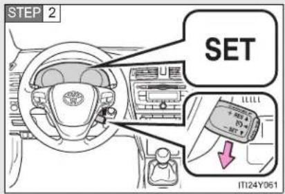
text_image
STEP 2 SET IT124Y061Accelerate or decelerate the vehicle to the desired speed, and push the lever down to set the speed.
"SET" indicator will come on.
The vehicle speed at the moment the lever is released becomes the set speed.
*: If equipped
■ Adjusting the set speed
To change the set speed, operate the lever until the desired set speed is obtained.

text_image
1 + RES 否 - SET 2 ITN24Y0041 Increase the speed
2 Decrease the speed
Fine adjustment: Momentarily move the lever in the desired direction.
Large adjustment: Hold the lever in the desired direction.
The set speed will be increased or decreased as follows:
Fine adjustment: By approximately 1.6 km/h (1 mph) each time the lever is operated.
Large adjustment: The set speed can be increased or decreased continually until the lever is released.
■ Canceling and resuming the constant speed control
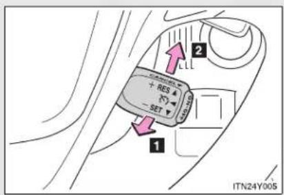
text_image
1 2 + RES - SET ITN24Y0051 Pulling the lever toward you cancels the constant speed control.
The speed setting is also canceled when the brakes are applied or the clutch pedal (manual transmission only) is depressed.
2 Pushing the lever up resumes the constant speed control.
Resuming is available when the vehicle speed is more than approximately 40 km/h (25 mph).
Cruise control can be set when
▶ Vehicles with a Multidrive
- The shift lever is in the "D" or range "4" or higher of "M" has been selected.
- Range "4" or higher has been selected by using the paddle shift. (vehicles with paddle shift switch)
● Vehicle speed is above approximately 40 km/h (25 mph).
▶ Vehicles with an automatic transmission
The shift lever is in "D".
- Range "4" or higher of "D" has been selected by using the paddle shift. (vehicles with paddle shift switch)
● Vehicle speed is above approximately 40 km/h (25 mph).
▶ Vehicles with a manual transmission
● Vehicle speed is more than approximately 40 km/h (25 mph).
■ Accelerating after setting the vehicle speed
- The vehicle can be accelerated normally. After acceleration, the set speed resumes.
- Even without canceling the cruise control, the set speed can be increased by first accelerating the vehicle to the desired speed and then pushing the lever down to set the new speed.
■ Automatic cruise control cancelation
Cruise control will stop maintaining the vehicle speed in any of the following situations.
- Actual vehicle speed falls more than approximately 16 km/h (10 mph) below the preset vehicle speed.
At this time, the memorized set speed is not retained.
● Actual vehicle speed is below approximately 40 km/h (25 mph).
• VSC is activated. - Speed limiter is activated (if equipped).
If the cruise control indicator light flashes
Press the "ON-OFF" button once to deactivate the system, and then press the button again to reactivate the system.
If the cruise control speed cannot be set or if the cruise control cancels immediately after being activated, there may be a malfunction in the cruise control system. Have the vehicle inspected by any authorized Toyota dealer or repairer, or another duly qualified and equipped professional.

CAUTION
■ To avoid operating the cruise control by mistake
Switch the cruise control off using the "ON-OFF" button when not in use.
■ Situations unsuitable for cruise control
Do not use cruise control in any of the following situations.
Doing so may result in loss of control and could cause an accident resulting in death or serious injury.
In heavy traffic
- On roads with sharp bends
- On winding roads
- On slippery roads, such as those covered with rain, ice or snow
- On steep hills
Vehicle speed may exceed the set speed when driving down a steep hill.
- When your vehicle is towing a trailer or during emergency towing
2-4. Using other driving systems
Dynamic radar cruise control\*
Dynamic radar cruise control supplements conventional cruise control with a vehicle-to-vehicle distance control. In the vehicle-to-vehicle distance control mode, the vehicle automatically accelerates or decelerates in order to maintain a set following distance from vehicles ahead.

text_image
1 SET 2 3 120 km/h 4 5 ITI24Y067a1 Indicators
2 Display
3 Set speed
4 Vehicle-to-vehicle distance button
5 Cruise control switch
*: If equipped
2-4. Using other driving systems
Setting the vehicle speed (vehicle-to-vehicle distance control mode)
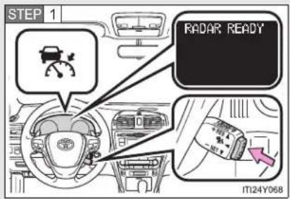
text_image
STEP 1 RADAR READY IT124Y068Press the "ON-OFF" button to activate the cruise control.
Dynamic radar cruise control indicator will come on.
Press the button again to deactivate the cruise control.
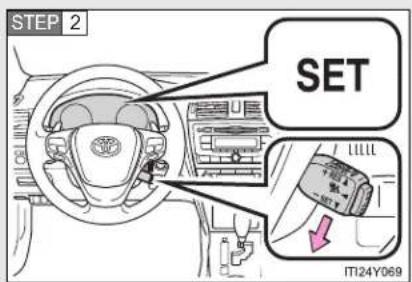
text_image
STEP 2 SET L1111 ITI24Y069Accelerate or decelerate the vehicle to the desired speed, and push the lever down to set the speed.
"SET" indicator will come on.
The vehicle speed at the moment the lever is released becomes the set speed.
■ Adjusting the set speed
To change the set speed, operate the lever until the desired set speed is displayed.
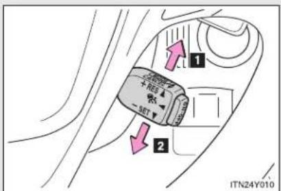
text_image
1 2 ITN24Y0101 Increase the speed
2 Decrease the speed
Fine adjustment: Momentarily move the lever in the desired direction.
Large adjustment: Hold the lever in the desired direction.
In the vehicle-to-vehicle distance control mode, the set speed will be increased or decreased as follows:
- When the set speed is shown in "MPH"
Fine adjustment: By approximately 8 km/h (5 mph) each time the lever is operated
Large adjustment: By approximately 8 km/h (5 mph) for each 0.75 seconds the lever is held
2-4. Using other driving systems
- When the set speed is shown in "km/h"
Fine adjustment: By approximately 5 km/h (3.1 mph) each time the lever is operated
Large adjustment: By approximately 5 km/h (3.1 mph) for each 0.75 seconds the lever is held
In the constant speed control mode ( P. 290), the set speed will be increased or decreased as follows:
Fine adjustment: By approximately 1.6 km/h (1 mph) each time the lever is operated
Large adjustment: The set speed can be increased or decreased continually until the lever is released.
■ Changing the vehicle-to-vehicle distance
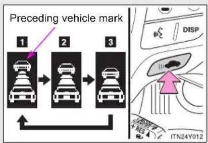
text_image
Preceding vehicle mark 1 2 3 DISP ITN24Y012Pressing the button changes the vehicle-to-vehicle distance as follows:
1 Long
2 Medium
3 Short
Vehicles with smart entry & start system:
The vehicle-to-vehicle distance is set automatically to long mode when the "ENGINE START STOP" switch is turned to IGNITION ON mode.
If a vehicle is running ahead of you, the preceding vehicle mark will also be displayed.
Vehicles without smart entry & start system:
The vehicle-to-vehicle distance is set automatically to long mode when the engine switch is turned to the "ON" position.
If a vehicle is running ahead of you, the preceding vehicle mark will also be displayed.
2-4. Using other driving systems
■ Vehicle-to-vehicle distance settings
Select a distance from the table below. Note that the distances shown correspond to a vehicle speed of 80 km/h (50 mph). Vehicle-to-vehicle distance increases/decreases in accordance with vehicle speed.
| Distance options Vehicle-to-vehicle distance |
| Long Approximately 50 m (160 ft.) |
| Medium Approximately 40 m (130 ft.) |
| Short Approximately 30 m (100 ft.) |
- Canceling and resuming the speed control
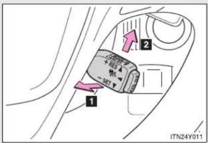
text_image
1 2 + SET ITN24Y0111 Pulling the lever toward you cancels the cruise control.
The speed setting is also canceled when the brakes are applied.
2 Pushing the lever up resumes the cruise control and returns vehicle speed to the set speed.
Resuming is available when the vehicle speed is more than approximately 40 km/h (25 mph).
Driving in vehicle-to-vehicle distance control mode
This mode employs a radar sensor to detect the presence of vehicles up to approximately 120 m (400 ft.) ahead, determines the current vehicle-to-vehicle following distance, and operates to maintain a suitable following distance from the vehicle ahead.
Note that vehicle-to-vehicle distance will close in when traveling on long downhill slopes.
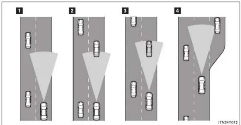
text_image
1 2 3 4 ITN24Y0132-4. Using other driving systems
1 Example of constant speed cruising
When there are no vehicles ahead
The vehicle travels at the speed set by the driver. The desired vehicle-to-vehicle distance can also be set by operating the vehicle-to-vehicle distance control.
2 Example of deceleration cruising
When the vehicle ahead is driving slower than the set speed
When a vehicle is detected running ahead of you, the system automatically decelerates your vehicle. When a greater reduction in vehicle speed is necessary, the system applies the brakes. A warning tone warns you when the system cannot decelerate sufficiently to prevent your vehicle from closing in on the vehicle ahead.
3 Example of follow-up cruising
When following a vehicle driving slower than the set speed
The system continues follow-up cruising while adjusting for changes in the speed of the vehicle ahead in order to maintain the vehicle-to-vehicle distance set by the driver.
4 Example of acceleration
When there are no longer any vehicles ahead driving slower than the set speed
The system accelerates until the set speed is reached. The system then returns to constant speed cruising.
Approach warning
When your vehicle is too close to a vehicle ahead, and sufficient automatic deceleration via the cruise control is not possible, the display will flash and the buzzer will sound to alert the driver. An example of this would be if another driver cuts in front of you while you are following a vehicle. Apply the brakes to ensure an appropriate vehicle-to-vehicle distance.
■ Warning may not occur when
In the following instances, there is a possibility that the warnings will not occur:
- When the speed of the vehicle ahead matches or exceeds your vehicle speed
- When the vehicle ahead is traveling at an extremely slow speed
- Immediately after the cruise control speed was set
- At the instant the accelerator is applied
Selecting conventional constant speed control mode
Constant speed control mode differs from vehicle-to-vehicle distance control mode. When constant speed control mode is selected, your vehicle will maintain a set speed regardless of whether or not there are other vehicles in the lane ahead.
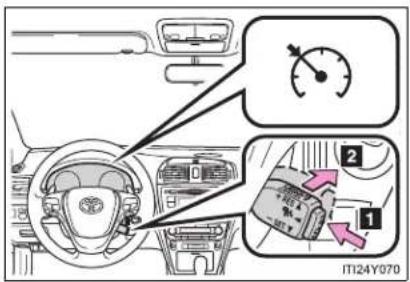
text_image
Diagram of car interior with labeled parts and a speedometer, showing dashboard and gear shift indicators1 Press the "ON-OFF" button to activate the cruise control.
Press the button again to deactivate the cruise control.
2 Switch to constant speed control mode.
(Push the lever forward and hold for approximately one second.)
Cruise control indicator will come on.
When in constant speed control mode, to return to vehicle-to-vehicle distance control mode, push the lever forward again and hold for approximately 1 second.
After the desired speed has been set, it is not possible to return to vehicle-to-vehicle distance control mode.
Vehicles with smart entry & start system:
If "ENGINE START STOP" switch is turned OFF and then turned to IGNITION ON mode again, the vehicle will automatically return to vehicle-to-vehicle distance control mode.
Vehicles without smart entry & start system:
If the engine switch is turned off and then turned to the "ON" position again, the vehicle will automatically return to vehicle-to-vehicle distance control mode.
Adjusting the speed setting:
→P. 283
Canceling and resuming the speed setting: →P. 286
■ Dynamic radar cruise control can be set when
- The shift lever is in "D".
- Range "4" or higher of "D" has been selected by using the paddle shift. (vehicles with paddle shift switch)
● Vehicle speed is above approximately 50 km/h (30 mph).
■ Accelerating after setting the vehicle speed
The vehicle can accelerate normally. After acceleration, the set speed resumes. However, during vehicle-to-vehicle distance control mode, the vehicle speed may decrease below the set speed in order to maintain the distance to the vehicle ahead.
■ Automatic cancelation of vehicle-to-vehicle distance control
Vehicle-to-vehicle distance control driving is automatically canceled in the following situations:
● Actual vehicle speed falls below approximately 40 km/h (25 mph).
• VSC is activated.
- The sensor cannot operate correctly because it is covered in some way.
- The windshield wipers are operating at high speed (when the wiper switch is set to the "AUTO" mode or the high speed wiper operation position).
If vehicle-to-vehicle distance control driving is automatically canceled for any other reason, there may be a malfunction in the system. Contact any authorized Toyota dealer or repairer, or another duly qualified and equipped professional.
■ Automatic cancelation of constant speed control
The cruise control will stop maintaining the vehicle speed in the following situations:
- Actual vehicle speed is more than approximately 16 km/h (10 mph) below the set vehicle speed.
At this time, the memorized set speed is not retained.
● Actual vehicle speed falls below approximately 40 km/h (25 mph).
• VSC is activated. - Speed limiter is activated. (if equipped)
■ Radar sensor and grille cover
Always keep the sensor and grille cover clean to ensure that the vehicle-to-vehicle distance control operates properly. (Some obstructions, such as snow, ice and plastic objects, cannot be detected by the obstruction sensor.) Dynamic radar cruise control is canceled if an obstruction is detected.
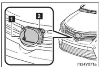
text_image
1 2 ITI24Y071a1 Grille cover
2 Radar sensor
■ Warning lights, messages and buzzers for dynamic radar cruise control
Warning lights, messages and buzzers are used to indicate a system malfunction or to inform the driver of the need for caution while driving.
(→P. 624)
2-4. Using other driving systems
Certification
| Hereby, DENSO CORPORATION declares that this DNMWR004 is in compliance with the essential requirements and other relevant provisions of Directive 1999/5/EC. |
| Hér með lýsir DENSO CORPORATION yfir því að DNMWR004 er í samræmi við grunnkröfur og aðrar kröfur, sem gerðar eru í tilskipun 1999/5/EC. |
| Con la presente DENSO CORPORATION dichiara che questo DNMWR004 è conforme ai requisiti essenziali ed alle altre disposizioni pertinenti stabilite dalla direttiva 1999/5/CE. |
| Käesolevaga kinnitab DENSO CORPORATION seadme DNMWR004 vastavust direktiivi 1999/5/EÜ põhinõuetele ja nimetatud direktiivist tulenevatele teistele asjakohastele sätetele. |
| Hierbij verklaart DENSO CORPORATION dat het toestel DNMWR004 in overeenstemming is met de essentiële eisen en de andere relevante bepalingen van richtlijn 1999/5/EG. |
| ME THN ΠΑΡΟΥΣΑ DENSO CORPORATION ΔΗΛΩΝΕΙ OTI DNMWR004 ΣΥΜΜΟΡΦΩΝ ΕΤΑΙ ΠΡΟΣ ΤΙΣ ΟΥΣΙΩΔΕΙΣ ΑΠΑΙΤΗΣΕΙΣ ΚΑΙ ΤΙΣ ΛΟΙΠΕΣ ΣΧΕΤΙΚΕΣ ΔΙΑΤΑΞΕΙΣ ΤΗΣ ΟΔΗΓΙΑΣ 1999/5/EK. |
| Härmed intygar DENSO CORPORATION att denna DNMWR004 står I överensstämmelse med de väsentliga egenskapskrav och övriga relevanta bestämmelser som framgår av direktiv 1999/5/EG. |
| Por medio de la presente DENSO CORPORATION declara que el DNMWR004 cumple con los requisitos esenciales y cualesquiera otras disposiciones aplicables o exigibles de la Directiva 1999/5/CE. |
| DENSO CORPORATION týmto vyhlasuje, že DNMWR004 splna základné požiadavky a všetky príslušné ustanovenia Smernice 1999/5/ES. |
| DENSO CORPORATION izjavlja, da je ta DNMWR004 v skladu z bistvenimi zahtevami in ostalimi relevantními določili direktive 1999/5/ES. |
| DENSO CORPORATION tímto prohlašuje, že tento DNMWR004 je ve shodě se základními požadavky a daišími príslušnými ustanoveními směrnice 1999/5/ES. |
| Undertegnede DENSO CORPORATION erklærer herved, at følgende udstyr DNMWR004 overholder de væsentlige krav og øvrige relevante krav i direktiv 1999/5/EF. |
| Hiermit erklärt DENSO CORPORATION, dass sich das Gerät DNMWR004 in Übereinstimmung mit den grundlegenden Anforderungen und den übrigen einschlägigen Bestimmungen der Richtlinie 1999/5/EG befindet. |
| DENSO CORPORATION erklærer herved at utstyret DNMWR004 er i samsvar med de grunnleggende krav og øvrige relevante krav i direktiv 1999/5/EF. |
| Alulírott, DENSO CORPORATION nyilatkozom, hogy a DNMWR004 megfelel a vonatkozó alapvető követelményeknek és az 1999/5/EC irányelv egyéb előírásainak. |
| DENSO CORPORATION vakuuttaa täten että DNMWR004 tyyppinen laite on direktiivin 1999/5/EY oleellisten vaatimusten ja sitä koskevien direktiivin muiden ehtojen mukainen. |
| Par la présente DENSO CORPORATION déclare que l'appareil DNMWR004 est conforme aux exigences essentielles et aux autres dispositions pertinentes de la directive 1999/5/CE. |
| Niniejszym DENSO CORPORATION oświadcza, że DNMWR004 jest zgodny z zasadniczymi wymogami oraz pozostałymi stosownymi postanowieniami Dyrektywy 1999/5/EC. |
| DENSO CORPORATION declara que este DNMWR004 está conforme com os requisitos essenciais e outras disposições da Directiva 1999/5/CE. |
| Hawnhekk, DENSO CORPORATION, jiddikjara li dan DNMWR004 jikkonforma mal-ħtigijiet essenzjali u ma provvedimenti oħrajn relevanti li hemm fid-Dirrettiva 1999/5/EC. |
| Ar šo, DENSO CORPORATION, deklarē, ka DNMWR004 atbilst Direktīvas 1999/5/EK būtiskajām prasībām un citiem ar to saistītajiem noteikumiem. |
| Šiuo DENSO CORPORATION deklaruoja, kad šis DNMWR004 atitinka esminius reikalavimus ir kitas 1999/5/EB Direktyvos nuostatas. |

CAUTION
■ Before using dynamic radar cruise control
Do not overly rely on vehicle-to-vehicle distance control.
Be aware of the set speed. If automatic deceleration/acceleration is not appropriate, adjust the vehicle speed, as well as the distance between your vehicle and vehicles ahead by applying the brakes etc.
■ Cautions regarding the driving assist systems
Observe the following precautions.
Failure to do so may cause an accident resulting in death or serious injury.
• Assisting the driver to measure following distance
The dynamic radar cruise control is only intended to help the driver in determining the following distance between the driver's own vehicle and a designated vehicle travelling ahead. It is not a mechanism that allows careless or inattentive driving, and it is not a system that can assist the driver in low-visibility conditions. It is still necessary for driver to pay close attention to the vehicle's surroundings.
• Assisting the driver to judge proper following distance
The dynamic radar cruise control determines whether the following distance between the driver's own vehicle and a designated vehicle traveling ahead is appropriate or not. It is not capable of making any other type of judgement. Therefore, it is absolutely necessary for the driver to remain vigilant and to determine whether or not there is a possibility of danger in any given situation.
• Assisting the driver to operate the vehicle
The dynamic radar cruise control has no capability to prevent or avoid a collision with a vehicle traveling ahead. Therefore, if there is ever any danger, the driver must take immediate and direct control of the vehicle and act appropriately in order to ensure the safety of all involved.

CAUTION
■ To avoid inadvertent cruise control activation
Switch the cruise control off using the "ON-OFF" button when not in use.
■ Situations unsuitable for dynamic radar cruise control
Do not use dynamic radar cruise control in any of the following situations.
Doing so may result in inappropriate speed control and could cause an accident resulting in death or serious injury.
In heavy traffic
- On roads with sharp bends
- On winding roads
- On slippery roads, such as those covered with rain, ice or snow
- On steep downhills, or where there are sudden changes between sharp up and down gradients
Vehicle speed may exceed the set speed when driving down a steep hill.
• At entrances to expressways
- When weather conditions are bad enough that they may prevent the sensors from functioning correctly (fog, snow, sandstorm, heavy rain, etc.)
- When an approach warning buzzer is heard often
- When your vehicle is towing a trailer or during emergency towing

CAUTION
■ When the sensor may not be correctly detecting the vehicle ahead
Apply the brakes as necessary when any of the following types of vehicles are in front of you.
As the sensor may not be able to correctly detect these types of vehicles, the approach warning ( P. 289) will not be activated, and a fatal or serious accident may result.
• Vehicles that cut in suddenly
• Vehicles traveling at low speeds
• Vehicles that are not moving
- Vehicles with small rear ends (trailers with no load on board etc.)
- Motorcycles traveling in the same lane
■ Conditions under which the vehicle-to-vehicle distance control may not function correctly
Apply the brakes as necessary in the following conditions as the radar sensor may not be able to correctly detect vehicles ahead, and a fatal or serious accident may result:
- When water or snow thrown up by the surrounding vehicles hinders the functioning of the sensor
- When your vehicle is pointing upwards (caused by a heavy load in the trunk etc.)
- When the road curves or when the lanes are narrow
- When steering wheel operation or your position in the lane is unstable
- When the vehicle ahead of you decelerates suddenly

CAUTION
■ Handling the radar sensor
Observe the following to ensure the cruise control system can function effectively.
Otherwise, the system may not function correctly and could result in an accident.
- Keep the sensor and grille cover clean at all times.
Clean the sensor and grille cover with a soft cloth so you do not mark or damage them. - Do not subject the sensor or surrounding area to a strong impact.
If the sensor moves even slightly off position, the system may malfunction. If the sensor or surrounding area is subject to a strong impact, always have the area inspected and adjusted by any authorized Toyota dealer or repairer, or another duly qualified and equipped professional. - Do not disassemble the sensor.
- Do not attach accessories or stickers to the sensor, grille cover or surrounding area.
- Do not modify or paint the sensor and grille cover.
- Do not replace them with non-genuine parts.
2-4. Using other driving systems
Speed limiter\*
A desired maximum speed can be set using the cruise control switch.
The speed limiter prevents vehicle speed from exceeding the set speed.
Setting the vehicle speed
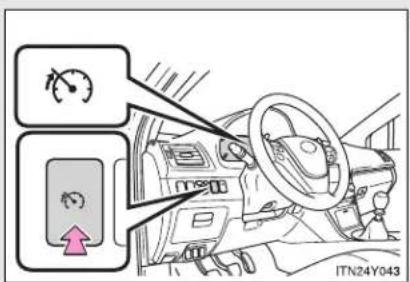
text_image
Diagram showing vehicle steering wheel and speedometer controls with directional arrows and a pink arrow indicating rotation direction.Press the switch to activate the speed limiter.
Press the switch once more to deactivate the speed limiter.

text_image
SPEED LIMIT 123 km/h IT124Y062aAccelerate or decelerate to the desired speed and push the lever down to set the desired maximum speed.
*: If equipped
■ Adjusting the speed setting

text_image
1 + RES - SET 2 ITN24Y0041 Increase speed
2 Decrease speed
Hold the lever until the desired speed setting is obtained.
Fine adjustment of the set speed can be made by lightly pushing the lever up or down and releasing it.
■ Canceling and resuming the speed limiter
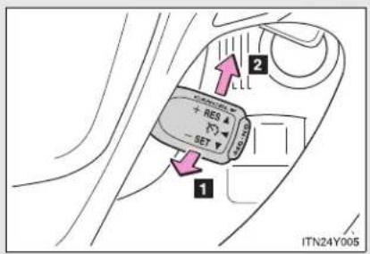
text_image
1 2 + RES - SET ITN24Y0051 Cancel
Pull the lever towards you to cancel the speed limiter.
2 Resume
To resume use of the speed limiter, push the lever up.
■ Speed limiter can be set when
The vehicle speed is more than approximately 30 km/h (18 mph).
Exceeding the set speed
In the following situations, the vehicle speed exceeds the set speed:
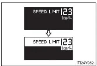
text_image
SPEED LIMIT 123 kW ↓ SPEED LIMIT 123 kW ITI24Y082- When fully depressing the accelerator pedal
- When driving down a hill
■ Automatic speed limiter cancellation
The set speed is automatically canceled when the cruise control is activated.
■ If the speed limiter indicator flashes
It may indicate a malfunction in the system. Contact any authorized Toyota dealer or repairer, or another duly qualified and equipped professional.

CAUTION
■ To avoid operating the speed limiter by mistake
Keep the speed limiter switch off when not in use.
■ Situations unsuitable for speed limiter
Do not use the speed limiter in either of the following situations.
Doing so may result in control of the vehicle being lost and could cause a serious or fatal accident.
- On slippery roads, such as those covered with rain, ice or snow
- On steep hills
- When towing a trailer or emergency towing
2-4. Using other driving systems
Toyota parking assist-sensor\*
Toyota parking assist-sensor uses sensors in the corners and rear of the vehicle to detect the distance between the vehicle and any obstacles, and informs the driver of this distance using the warning beeps.
Sensor types
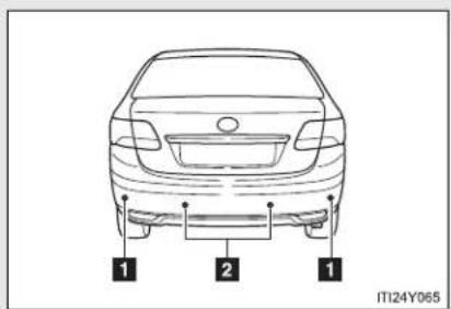
text_image
1 2 1 ITI24Y0651 Rear corner sensor
2 Back sensors
Toyota parking assist-sensor switch
▶ Left-hand drive vehicles
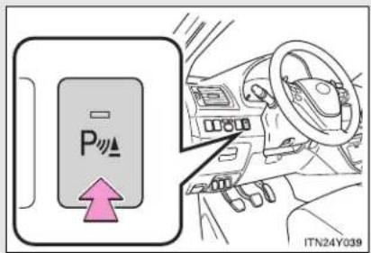
text_image
P ITN24Y039On/off
To turn the system on, press the switch. The indicator light comes on to inform the driver that the system is operational.
To turn the system off, press the switch again.
*: If equipped
2-4. Using other driving systems
▶ Right-hand drive vehicles

text_image
P IT124Y072Sensor detection distance and buzzer
▶ Back sensors
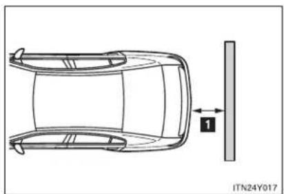
natural_image
Top-down schematic of a car showing front and side views with a vertical guide bar (no text or symbols)| Distance shown as Huzzer | |
| 160 to 67.5 cm (5.3 to 2.2 ft.) Long | |
| 67.5 to 47.5 cm (2.2 to 1.6 ft.) Medium | |
| 47.5 to 35 cm (1.6 to 1.1 ft.) Short | |
| Less than 35 cm (1.1 ft.) Continuous |
▶ Corner sensors
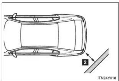
natural_image
Top-down line drawing of a car showing front and side views with a numbered annotation (no text or symbols on the car itself)| Distance shown as ☐uzzer | |
| 45 to 37.5 cm (1.5 to 1.2 ft.) Medium | |
| 37.5 to 25 cm (1.2 to 0.8 ft.) Short | |
| Less than 25 cm (0.8 ft.) Continuous |
Obstacle detection range

text_image
1 2 IT24Y0811 Approx. 45 cm (1.5 ft.)
2 Approx. 160 cm (5.3 ft.)
The detection area of the sensors is shown to the left. If obstacles move too close to the sensors, they will not be detected.
The range of the sensors may change depending on the shape of the object etc.
■ The Toyota parking assist-sensor can be operated when
▶ Vehicles with smart entry & start system
The "ENGINE START STOP" switch is in IGNITION ON mode, and the shift lever is in the "R" position.
▶ Vehicles without smart entry & start system
The engine switch is in the "ON" position, and the shift lever is in the "R" position.
■ Sensor detection information
- Certain vehicle conditions and the surrounding environment may affect the ability of the sensor to correctly detect obstacles. Particular instances where this may occur are listed below.
- There is dirt, snow or ice on the sensor. (Wiping the sensor will resolve this problem.)
- The sensor is frozen. (Thawing the sensor will resolve this problem.)
- The sensor is covered in any way.
- In harsh sunlight or intense cold weather.
- When driving on bumpy, sloped or gravel roads, or over grass.
- If there is something producing ultrasonic waves nearby, such as another vehicle's horn, motorcycle engine noise, air braking sound from heavy-duty vehicles, or another vehicle using the park assist system.
- In heavy rain, or if water is splashed on the sensors.
- The vehicle is leaning considerably to one side.
- If a commercial fender pole or radio antenna is installed.
- If moving towards a high curb or a curb corner.
- If towing eyelet is installed on your vehicle.
- The bumper or sensor receives a strong impact.
- A non-genuine Toyota suspension (lowered suspension etc.) is installed.
In addition to the examples above, there are instances in which, because of their shapes, signs and other objects may be judged by the sensor to be closer than they are.
- The shape of the obstacle may prevent the sensor from detecting it. Pay particular attention to the following obstacles.
- Thin objects such as wire, fencing or rope.
- Objects that absorb sound waves, such as cotton or snow.
- Objects with sharp corners.
- Low objects.
- Objects where the upper section projects out over the lower section.

CAUTION
■ When using the Toyota parking assist-sensor
Observe the following precautions.
Failing to do so may result in the vehicle being unable to be driven safely and possibly cause an accident.
- Do not use the sensor at speeds in excess of 10 km/h (6 mph).
- Do not install accessories within the sensors' detection areas.

NOTICE
■ When washing the vehicle
Do not apply intensive bursts of water or steam to the sensor area. Doing so may result in the sensor malfunctioning.
2-4. Using other driving systems Rear view monitor system\*
The rear view monitor system assists the driver by displaying an image of the view behind the vehicle while reversing. The image is displayed in reverse on the screen. This allows the image to appear in the same manner as that of the rear view mirror.
▶ Vehicles with a "touch screen"
Refer to the "touch screen" Owner's Manual".
▶ Vehicles without a "touch screen"

text_image
Diagram illustrating car gear shift and steering system with labeled components and directional arrowsRear view image is displayed on the inside rear view mirror when the shift lever is in "R".
This reversed image is a similar image to the one on the inside rear view mirror.
If you move the lever out of "R", the screen is turned off.
*: If equipped
■ Rear view monitor guide lines
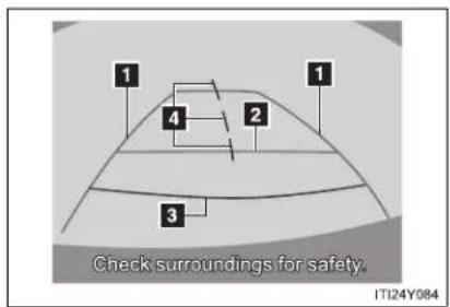
text_image
Check surroundings for safety. IT124Y084Guide lines are displayed on the screen.
Guide lines shown differ from those shown on the actual screen.
1 Vehicle width extension guide line (blue)
These lines indicate the estimated vehicle width extension.
2 Distance guide line (blue)
This line indicates a position on the ground about 1 m (3 ft.) behind on the ground of the rear bumper of your vehicle.
3 Distance guide line (red)
This line indicates a position on the ground about 0.5 m (1.5 ft.) behind on the ground of the rear bumper of your vehicle.
4 Vehicle center guide lines (blue)
These lines indicate the estimated vehicle center on the ground.
The rear view monitor system can be operated when
▶ Vehicles with smart entry & start system
The "ENGINE START STOP" switch is in IGNITION ON mode, and the shift lever is in the "R" position.
▶ Vehicles without smart entry & start system
The engine switch is in the "ON" position, and the shift lever is in the "R" position.
■ Switching the screen
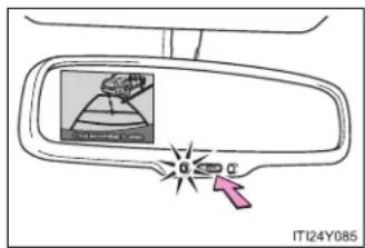
text_image
IT124Y085When the screen is displayed, press the "AUTO" button on the inside rear view mirror to switch the screen ON/OFF mode.
Screen ON mode: Green indicator comes on.
Screen OFF mode: Amber indicator comes on.
■ When using the rear view monitor system
The anti-glare function of the inside rear view mirror will be canceled.
■ Automatic shut off
The display will be turned off automatically after 5 minutes.
■ Displayed area

natural_image
Technical line drawing of a car showing top and side views with no text or symbols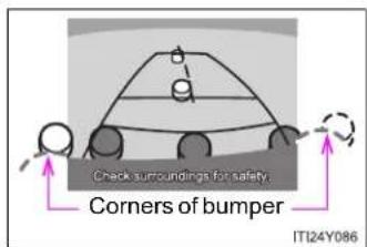
text_image
Check surroundings for safety. Corners of bumper ITI24Y086The area covered by the camera is limited. Objects which are close to either corner of the bumper or under the bumper cannot be seen on the screen.
The area displayed on the screen may vary according to vehicle orientation or road conditions.
The camera uses a special lens.
The distance of the image that appears on the screen differs from the actual distance.
- Driving precautions
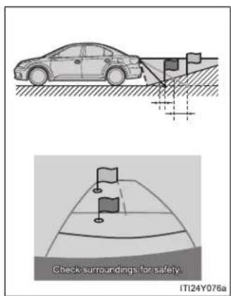
text_image
Check surroundings for safety- IT124Y076aWhen the grade behind the vehicle slopes up sharply, objects appear to be farther away than they actually are.
2-4. Using other driving systems
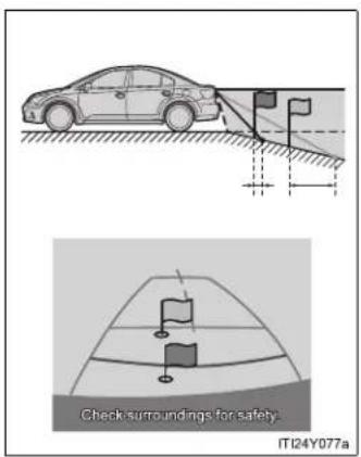
text_image
Check surroundings for safety. IT124Y077aWhen the grade behind the vehicle slopes down sharply, objects appear to be closer than they actually are.
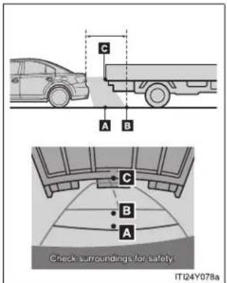
text_image
C A B C B A Check surroundings for safety IT124Y078aThe distance that appears on the screen between three-dimensional objects (such as vehicles) and flat surfaces (such as the road) and the actual distance differ as follows.
In reality, C = A < B (C and A are equally far away; B is farther than C and A). However, on the screen, the situation appears to be A < B < C.
On the screen, it appears that a truck is parking about 0.5 m (1.5 ft.) away. However, in reality if you back up to point A, you will hit the truck.
■ Rear view monitor system camera
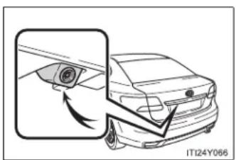
natural_image
Diagram of a car showing a camera lens interacting with the side panel, no text or symbols presentIn the following cases, it may become difficult to see the images on the screen, even when the system is functioning correctly.
- The vehicle is in a dark area, such as at night.
- The temperature near the lens is extremely high or low.
● Water droplets are on the camera lens or humidity is high, such as when it rains. - Foreign matter, such as snow or mud adheres to the camera lens.
- The sun or headlights are shining directly into the camera lens.
- A bright object such as a white wall is reflected in the mirror surface over the monitor.
● The camera has scratches or dirt on it.
2-4. Using other driving systems
Smear effect
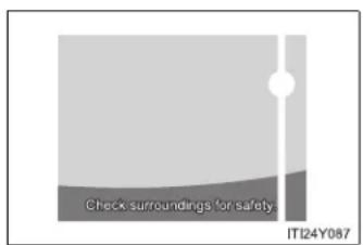
text_image
Check surroundings for safety. IT124Y087If a bright light (for example, sunlight reflected off the vehicle body) is picked up by the camera, a smear effect* peculiar to the camera may occur.
*:Smear effect — A phenomenon that occurs when a bright light (for example, sunlight reflected off the vehicle body) is picked up by the camera; when transmitted by the camera, the light source appears to have a vertical streak above and below it.
Flicker effect
When the camera is used under fluorescent lights, sodium lights, mercury lights etc., the lights and the illuminated areas may appear to flicker.

CAUTION
■ When using the rear view monitor system
Observe the following precautions to avoid an accident that could result in death or serious injuries.
- Never depend solely on the monitor system when reversing.
● Always check visually and with the mirrors to confirm your intended path is clear. - Use your own eyes to confirm the vehicle's surroundings, as the displayed image may become faint or dark, and moving images will be distorted, or not entirely visible when the outside temperature is low. When backing up, be sure to check behind and all around the vehicle visually and with the mirrors before proceeding.
● Always check the vehicle surrounding area, because the guide lines are ancillary lines. - The guide lines are ancillary lines and do not change even if the steering wheel is turned.
- Depicted distances between objects and flat surfaces differ from actual distances.
- Do not use the system if the trunk/back door is not completely closed.

NOTICE
Conditions which may affect the rear view monitor system
- If the back of the vehicle has been hit, the camera's position and mounting angle may have been changed. Contact any authorized Toyota dealer or repairer, or another duly qualified and equipped professional.
- Rapid temperature changes, such as when hot water is poured on the vehicle in cold weather, may cause the system to function abnormally.
- If the camera lens is dirty, it cannot transmit a clear image. Rinse with water and wipe with a soft cloth. If extremely dirty, wash with a mild cleanser and rinse.
- The displayed image may be darker and moving images may be slightly distorted when the system is cold.

NOTICE
Camera precautions
- As the camera has a water proof construction, do not detach, disassemble or modify it. This may cause incorrect operation.
- Do not subject the camera to a strong impact.
- If the camera lens becomes dirty, it cannot transmit a clear image. If water droplets, snow, or mud adhere to the lens, rinse with water and wipe with a soft cloth. If the lens is extremely dirty, wash it with a mild cleanser and rinse. Do not rub hard.
- Do not allow organic solvent, car wax, window cleaner or glass coat to adhere to the camera. If this happens, wipe it off as soon as possible.
- Do not strongly rub the camera lens. If the camera lens is scratched, it cannot transmit a clear image.
- When washing the vehicle, do not apply intensive bursts of water to the camera or camera area. Doing so may result in the camera malfunction.
- When replacing tires, please consult any authorized Toyota dealer or repairer, or another duly qualified and equipped professional. If you replace the tires, the area displayed on the screen may change.
2-4. Using other driving systems LKA (Lane-Keeping Assist)\*
While driving on a freeway or motor highway that has lane markers, this system recognizes the lanes using a camera as a sensor to assist the driver with staying in the lane. The LKA system has two functions.
Lane departure warning function
If the system judges that the vehicle may deviate from its lane, it alerts the driver using rapid beeping, indications on the multi-information display, and a sensory warning* given via the steering wheel.
*: A slight steering torque is applied for a short period of time in the direction of the center of the lane.
Lane keeping assist function
This function will be active when the vehicle-to-vehicle distance control mode of the cruise control ( P. 281) is set with vehicle speed above approx. 72 km/h (approx. 45 mph) and while the lane departure warning function is active. When the lane keeping assist function is active, a slight steering torque will be applied, to help the driver maintain the vehicle in a central position within the lane.
While the lane keeping assist function is active, sensory warnings will not occur.
*: If equipped
■ Turning the LKA system on
The lane departure warning function and lane keeping assist function will be activated depending on the recognition condition of lane markers, vehicle speed and the setting of radar cruise control (vehicle-to-vehicle distance control mode).

text_image
LKA 100 km/h LKA ITN24Y020Press the "LKA" switch to activate the system.
Press the switch again to turn the LKA system off.
- Operating conditions for each function
| “LKA” switch | Cruise control (vehicle-to-vehicle distance control mode) | Lane departure warning function *1 | Lane keeping assist function *2 |
| On | Off Available Not available | ||
| On(While cruising in vehicle-to-vehicle distance control mode with the set vehicle speed approx. 71 km/h [approx. 44 mph] or less) | Available Not available | ||
| On(While cruising in vehicle-to-vehicle distance control mode with the set vehicle speed approx. 72 km/h [approx. 45 mph] or more) | Available Available | ||
*1: Vehicle speed is between about 50 and 200 km/h (30 and 125 mph).
*2: Vehicle speed is between about 72 and 180 km/h (45 and 112 mph).
Indication on the multi-information display
While the LKA system is on, the lane line display and steering wheel display (in case of lane keeping assist function) are shown on the multi-information display to inform that the LKA system is on.

text_image
1 2 100 km/h 3 ITN24Y0211 Steering wheel display
The lane keeping assist function is active.
2 Dynamic radar cruise control display
3 Lane line display
When thin lines are shown:
A lane marking is not recognized by the system, or the LKA system functions are temporarily canceled. (When the lane keeping assist function is canceled, buzzer will beep twice.)
When solid lane lines are shown without steering wheel display:
The lane departure warning function is active.
■ Temporary cancellation of the LKA system functions
If any of the following occurs, the LKA system functions will be temporarily canceled. The functions will resume after the necessary operating conditions have returned.
- The turn signal lever is operated.
- The steering wheel is turned as far as necessary to cause the vehicle to change lanes.
The brake pedal is depressed.
However, the lane keeping assist function will not resume even after the brake pedal is released because depressing the brake pedal also cancels the dynamic radar cruise control (only lane departure warning function will resume).
- The vehicle speed deviates from the operating range of the LKA system functions. (The buzzer will beep twice when the lane keeping assist function is being canceled.)
- When the lane lines cannot be recognized while driving. (The buzzer will beep twice when the lane keeping assist function is being canceled.)
- The wiper operates continuously. (The buzzer will beep twice when the lane keeping assist function is being canceled.)
The buzzer may not beep when the LKA system functions are canceled because the notification of dynamic radar cruise control cancellation takes priority over the LKA system and cancels the function.
■ When the lane departure warning function is activated
The lane departure warning function will be temporarily canceled and will not resume until a few seconds elapse after it is activated.
■ Hands-free driving warning
If the steering wheel is not operated for about 15 seconds on a straight road or about 5 seconds on a curve, the buzzer will beep twice, indicators on the multi-information display will flash, and the lane keeping assist function will be temporarily canceled. If you drive the vehicle with your hands lightly touching the steering wheel, this may also be detected as hands-free driving.
■ When the vehicle has been parked in the sun
The LKA system functions may not be available for a while after driving has started. In such cases, turn the LKA system off and turn it on again after normal temperature returns. When the temperature in the cabin decreases and the temperature around the camera sensor becomes suitable for its operation, the functions will begin to operate.
■ Warning lights and messages for LKA
Warning lights and messages are used to indicate a system malfunction or to inform the driver of the need for caution while driving. (→P. 619)

CAUTION
■ Before using the LKA system
Do not rely on the LKA system to remain within a selected lane. The LKA system is not designed to enable inattentive driving. The steering wheel should be operated by the driver to maintain the vehicle in a suitable position within its lane. Always drive carefully.

CAUTION
■ Turn the LKA off while driving in any of the following conditions
Do not use LKA in any of the following situations.
Otherwise, the system may not function correctly and could result in an accident.
- When driving with snow tires, tire chains, a spare tire, or similar equipment.
- When driving with non-standard parts or aftermarket equipment installed. (including modified tires and suspensions, etc.)
- When towing a trailer.
- When there are objects or structures along the roadside that might be misinterpreted as lane markers (such as guardrails, curb, reflector posts, etc.).
- When there are wheel ruts, icy trademarks, etc. or if snow remains on the road surface.
- When there are shadows on the road running parallel with lane markers, or if a shadow covers the lane markers.
- When there are visible lines on the pavement from road repairs, or if the remains of old lane markers are still visible on the road.
- When driving on slippery roads, such as those covered with rain, ice or snow.
- When driving in a lane other than the driving or passing lanes on a freeway or highway.
- When driving on a road with lane closures due to maintenance, or when driving in a temporary lane.
- When driving on winding roads or roads that are rough or uneven.

NOTICE
In the following situations, the LKA will not work, or will not perform reliably
- When lane markers are interrupted or are not present, such as before a tollbooth.
- When lane markers are only on one side of the road.
- When driving on a sharp curve.
- When lanes are extremely narrow or extremely wide.
- When the vehicle leans to one side an unusual amount due to a heavy load or improper tire inflation pressure.
- When the following distance between your vehicle and the vehicle ahead is extremely short.
- When the lane markers are broken or "Raised pavement marker".
- When lane markers are obscured or partially obscured by sand, dirt, etc.
- When driving on a particularly bright road surface, such as concrete.
- When driving on a road surface that is bright due to reflected light.
- When driving in a location where the light level changes rapidly, such as the entrance to or exit from a tunnel.
- When sunlight or the headlights of oncoming vehicles are shining directly into the camera lens.
- When driving on roads that are branching or merging.
- When pavement lane markers are difficult to see due to rain, snow, fog, etc.
- When driving on a road surface that is wet due to rain, previous rainfall, standing water, etc.
- When the vehicle experiences strong up-and-down motion such as when driving on an extremely rough road or on a seam in the pavement.
- When headlight brightness is reduced due to dirt on the lenses, or when the headlights are misaligned.
- When driving with a strong crosswind.

NOTICE

Camera sensor
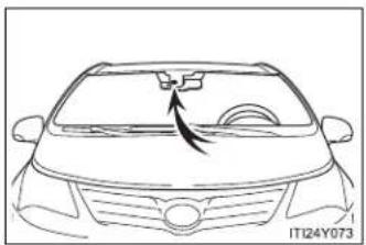
natural_image
Line drawing of a car's front grille and dashboard (no text or symbols)Observe the following to ensure that the LKA system functions correctly.
- Keep the windshield clean at all times.
LKA performance may deteriorate due to the presence of raindrops, condensation, ice or snow on the windshield. - Do not attach a sticker or other items to the windshield near the camera sensor.
- When adjusting the rear view mirror, make sure that it does not block the camera lens.
- When it is cold, using the heater with air blowing to the feet may allow the upper part of the windshield to fog up. This will have a negative effect on the images. In such a case, use the windshield defogger to provide warm, dry air to the windshield.
Do not place anything on the dashboard.
The camera sensor may recognize the image reflected on the windshield as lane markings by mistake.
Do not scratch the camera lens, or let it get dirty. - Do not change the installation position of the camera sensor or remove it. The direction of the camera sensor is precisely adjusted.
- Do not subject the camera sensor to strong impact or force, and do not disassemble the camera sensor.
2-4. Using other driving systems
Driving assist systems
To help enhance driving safety and performance, the following systems operate automatically in response to various driving situations. Be aware, however, that these systems are supplementary and should not be relied upon too heavily when operating the vehicle.
■ ABS (Anti-lock Brake System)
Helps to prevent wheel lock when the brakes are applied suddenly, or if the brakes are applied while driving on a slippery road surface.
Brake assist
Generates an increased level of braking force after the brake pedal is depressed, when the system detects a panic stop situation.
■ VSC (Vehicle Stability Control)
Helps the driver to control skidding when swerving suddenly or turning on slippery road surfaces.
■ TRC (Traction Control)
Helps to maintain drive power and prevent the front wheels from spinning when starting the vehicle or accelerating on slippery roads.
EPS (Electric Power Steering)
Employs an electric motor to reduce the amount of effort needed to turn the steering wheel.
■ VSC+ (Vehicle Stability Control+)
Provides cooperative control of the ABS, TRC, VSC and EPS.
Helps to maintain directional stability when swerving on slippery road surfaces by controlling steering performance.
■ PCS (Pre-Crash Safety) (if equipped)
→P. 333
Emergency brake signal (if equipped)
When the brakes are applied suddenly, the stop lights automatically flash to alert the vehicle behind.
When the TRC and VSC are operating

If the vehicle is in danger of slipping or if the front wheels spin, the slip indicator light flashes to indicate that the TRC/VSC have been engaged.
To disable TRC and/or VSC system
If the vehicle gets stuck in fresh snow or mud, the TRC and VSC systems may reduce power from the engine to the wheels. You may need to turn the system off to enable you to rock the vehicle in order to free it.
■ Turning off TRC
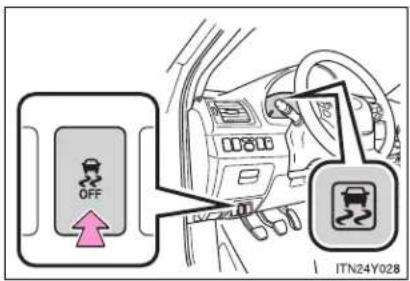
text_image
OFF ITN24Y028Quickly push and release the button to turn off TRC.
The slip indicator light should come on.
Push the button again to turn the system back on.
■ Turning off TRC and VSC
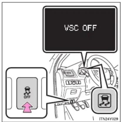
text_image
VSC OFF OFF ITN24Y029Push and hold the button for more than 3 seconds while the vehicle is stopped to turn off TRC and VSC.
The slip indicator light will come on and a message will be shown on the multi-information display.
Push the button again to turn the system back on.
■ Reactivation of the TRC/VSC systems after turning off the engine
Even after the TRC/VSC systems have been turned off, turning the engine off and then on again will automatically reactivate the TRC/VSC systems.
■ Reactivation of the TRC system linked to vehicle speed
When only the TRC system is turned off, the TRC system will turn on when vehicle speed increases. However, when both TRC and VSC systems are turned off, the systems will not turn on even when vehicle speed increases.
2-4. Using other driving systems
■ Sounds and vibrations caused by the ABS, brake assist, TRC and VSC
- A sound may be heard from the engine compartment when the engine is started or just after the vehicle begins to move. This sound does not indicate that a malfunction has occurred in any of these systems.
- Any of the following conditions may occur when the above systems are operating. None of these indicates that a malfunction has occurred.
- Vibrations may be felt through the vehicle body and steering.
- A motor sound may be heard after the vehicle comes to a stop.
- The brake pedal may pulsate slightly after the ABS is activated.
- The brake pedal may move down slightly after the ABS is activated.
EPS operation sound
When the steering wheel operates, a motor sound (whirring sound) may be heard. This does not indicate a malfunction.
■ Reduced effectiveness of EPS
The effectiveness of EPS is reduced to prevent the system from overheating when there is frequent steering input over an extended period of time. The steering wheel may feel heavy as a result. Should this occur, refrain from excessive steering input or stop the vehicle and turn the engine off. The system should return to normal after about 10 minutes.

CAUTION
Any of the following conditions may result in an accident which could cause death or serious injury:
The ABS does not operate effectively when
The limits of tire gripping performance have been exceeded.
The vehicle hydroplanes while driving at high speed on a wet or slick road.
■ Stopping distance when the ABS is operating may exceed that of normal conditions
The ABS is not designed to shorten the vehicle's stopping distance. Always maintain a safe distance from the vehicle in front of you in the following situations:
- When driving on dirt, gravel or snow-covered roads
- When driving with tire chains
- When driving over bumps in the road
- When driving over roads with potholes or roads with uneven roads
■ TRC may not operate effectively when
Directional control and power may not be achievable while driving on slippery road surfaces, even if the TRC is operating.
Do not drive the vehicle in conditions where stability and power may be lost.
■ When the VSC is activated
The slip indicator light flashes. Always drive carefully.
Reckless driving may cause an accident. Exercise particular care when the indicator light flashes.

CAUTION
■ When the TRC and VSC are off
Be especially careful and drive at a speed appropriate to the road conditions. As these are systems to ensure vehicle stability and driving force, do not turn off TRC and VSC unless necessary.
■ Replacing tires
Make sure that all tires are of the same size, brand, tread pattern and total load capacity. In addition, make sure that the tires are inflated to the specified tire pressure level.
The ABS and VSC systems will not function correctly if different tires are fitted on the vehicle.
Contact any authorized Toyota dealer or repairer, or another duly qualified and equipped professional for further information when replacing tires or wheels.
■ Handling of tires and suspension
Using tires with any kind of problem or modifying the suspension will affect the driving assist systems, and may cause the system to malfunction.
2-4. Using other driving systems
PCS (Pre-Crash Safety)\*
When the radar sensor detects possibility of a frontal collision, the pre-crash safety systems such as the brakes and seat belts are automatically engaged to lessen impact and injuries to occupants as well as vehicle damage.
■ Pre-crash seat belts
If the pre-crash sensor detects that a collision is unavoidable, the pre-crash safety system will retract the seat belt before the collision occurs.
The same will happen if the driver makes an emergency braking or loses control of the vehicle. ( P. 110)
However, when the VSC system is disabled, the system will not operate in the event of skidding.
■ Pre-crash brake assist
When there is a high possibility of a frontal collision, the system applies greater braking force in relation to how strongly the brake pedal is depressed.
■ Pre-crash braking
When there is a high possibility of a frontal collision, the system warns the driver using a warning light, warning display and buzzer. If the system determines that a collision is unavoidable, the brakes are automatically applied to reduce the collision speed. Pre-crash braking can be disabled using the pre-crash braking OFF switch.
Disabling pre-crash braking
▶ Type A
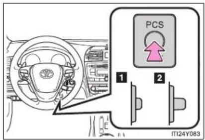
text_image
PCS 1 2 ITI24Y0831 Disabled
2 Enabled
The "PCS" warning light will turn on when the pre-crash braking is disabled.
▶ Type B
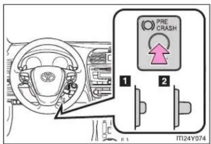
text_image
PRE CRASH 1 2 IT24Y0741 Disabled
2 Enabled
The "PCS" warning light will turn on when the pre-crash braking is disabled.
Radar sensor

natural_image
Technical illustration of a car's front wheel assembly with a magnified inset showing the component (no text or symbols present)Detects vehicles or other obstacles on or near the road ahead and determines whether a collision is imminent based on the position, speed, and heading of the obstacles.
Obstacles not detected
The sensor cannot detect plastic obstacles such as pylons. There may also be occasions when the radar sensor cannot detect pedestrians, animals, bicycles, motorcycles, trees, or snowdrifts.
The pre-crash safety is operational when
• Pre-crash seat belts (Type A):
- Vehicle speed is greater than about 30 km/h (19 mph).
- The system detects sudden braking or skidding.
- The front occupants are wearing a seat belt.
● Pre-crash seat belts (Type B):
• Vehicle speed is above 5 km/h (4 mph).
- The relative speed difference between your vehicle and another vehicle that is ahead of your vehicle, or the speed at which your vehicle is approaching an obstacle is greater than 30 km/h (19 mph).
- The front occupants are wearing a seat belt.
• Pre-crash brake assist:
• Vehicle speed is above 30 km/h (19 mph).
- The relative speed difference between your vehicle and another vehicle that is ahead of your vehicle, or the speed at which your vehicle is approaching an obstacle is greater than 30 km/h (19 mph).
• The brake pedal is depressed.
- Pre-crash braking:
- The pre-crash braking OFF switch is not pressed.
• Vehicle speed is above 15 km/h (10 mph). - The relative speed difference between your vehicle and another vehicle that is ahead of your vehicle, or the speed at which your vehicle is approaching an obstacle is greater than 15 km/h (10 mph).
2-4. Using other driving systems
■ Conditions that may trigger the system even if there is no possibility of a collision
- When there is an object by the roadside at the entrance to a curve
- When passing an oncoming vehicle on a curve
- When driving over a narrow iron bridge
- When there is a metal object on the road surface
- When driving on an uneven road surface
- When passing an oncoming vehicle on a right-turn (right-hand drive vehicles) or left-turn (left-hand drive vehicles)
- When your vehicle rapidly closes on the vehicle in front
- When a grade separation/interchange, sign, billboard, or other structure appears to be directly in the vehicle's line of travel
- When the steep angle of the road causes a metal object located beneath the road surface to be seen ahead of the vehicle
- When an extreme change in vehicle height occurs
- When the axis of the radar is out of adjustment
- When passing through certain toll gates
- When passing through an overpass
When the system is activated in the situations described above there is also a possibility that the seat belts will retract quickly and the brakes will be applied with a force greater than normal. When the seat belt is locked in the restricted position, stop the vehicle in a safe place, release the seat belt and refasten.
■ Situations in which the pre-crash safety system does not function properly
The system may not function effectively in situations such as the following:
- On roads with sharp bends or uneven surfaces
- If a vehicle suddenly moves in front of your vehicle, such as at an intersection
- If a vehicle suddenly cuts in front of your vehicle, such as when overtaking
- In inclement weather such as heavy rain, fog, snow or sand storms
- When your vehicle is skidding with the VSC system off
- When the axis of the radar is out of adjustment
- When an extreme change in vehicle height occurs
■ When there is a malfunction in the system
Warning lights and/or warning messages will turn on or flash. (→P. 624)
2-4. Using other driving systems
Certification
| Hereby, DENSO CORPORATION declares that this DNMWR004 is in compliance with the essential requirements and other relevant provisions of Directive 1999/5/EC. |
| Hér með lýsir DENSO CORPORATION yfir því að DNMWR004 er í samræmi við grunnkröfur og aðrar kröfur, sem gerðar eru í tilskipun 1999/5/EC. |
| Con la presente DENSO CORPORATION dichiara che questo DNMWR004 è conforme ai requisiti essenziali ed alle altre disposizioni pertinenti stabilite dalla direttiva 1999/5/CE. |
| Käesolevaga kinnitab DENSO CORPORATION seadme DNMWR004 vastavust direktiivi 1999/5/EÜ põhinõuetele ja nimetatud direktiivist tulenevatele teistele asjakohastele sätetele. |
| Hierbij verklaart DENSO CORPORATION dat het toestel DNMWR004 in overeenstemming is met de essentiële eisen en de andere relevante bepalingen van richtlijn 1999/5/EG. |
| ME THN ΠΑΡΟΥΣΑ DENSO CORPORATION ΔΗΛΩΝΕΙ OTI DNMWR004 ΣΥΜΜΟΡΦΩΝ ΕΤΑΙ ΠΡΟΣ ΤΙΣ ΟΥΣΙΩΔΕΙΣ ΑΠΑΙΤΗΣΕΙΣ ΚΑΙ ΤΙΣ ΛΟΙΠΕΣ ΣΧΕΤΙΚΕΣ ΔΙΑΤΑΞΕΙΣ ΤΗΣ ΟΔΗΓΙΑΣ 1999/5/EK. |
| Härmed intygar DENSO CORPORATION att denna DNMWR004 står I överensstämmelse med de väsentliga egenskapskrav och övriga relevanta bestämmelser som framgår av direktiv 1999/5/EG. |
| Por medio de la presente DENSO CORPORATION declara que el DNMWR004 cumple con los requisitos esenciales y cualesquiera otras disposiciones aplicables o exigibles de la Directiva 1999/5/CE. |
| DENSO CORPORATION týmto vyhlasuje, že DNMWR004 splna základné požiadavky a všetky príslušné ustanovenia Smernice 1999/5/ES. |
| DENSO CORPORATION izjavlja, da je ta DNMWR004 v skladu z bistvenimi zahtevami in ostalimi relevantními določili direktive 1999/5/ES. |
| DENSO CORPORATION tímto prohlašuje, že tento DNMWR004 je ve shodě se základními požadavky a daišími príslušnými ustanoveními směrnice 1999/5/ES. |
| Undertegnede DENSO CORPORATION erklærer herved, at følgende udstyr DNMWR004 overholder de væsentlige krav og øvrige relevante krav i direktiv 1999/5/EF. |
| Hiermit erklärt DENSO CORPORATION, dass sich das Gerät DNMWR004 in Übereinstimmung mit den grundlegenden Anforderungen und den übrigen einschlägigen Bestimmungen der Richtlinie 1999/5/EG befindet. |
| DENSO CORPORATION erklærer herved at utstyret DNMWR004 er i samsvar med de grunnleggende krav og øvrige relevante krav i direktiv 1999/5/EF. |
| Alulírott, DENSO CORPORATION nyilatkozom, hogy a DNMWR004 megfelel a vonatkozó alapvető követelményeknek és az 1999/5/EC irányelv egyéb előírásainak. |
| DENSO CORPORATION vakuuttaa täten että DNMWR004 tyyppinen laite on direktiivin 1999/5/EY oleellisten vaatimusten ja sitä koskevien direktiivin muiden ehtojen mukainen. |
| Par la présente DENSO CORPORATION déclare que l'appareil DNMWR004 est conforme aux exigences essentielles et aux autres dispositions pertinentes de la directive 1999/5/CE. |
| Niniejszym DENSO CORPORATION oświadcza, że DNMWR004 jest zgodny z zasadniczymi wymogami oraz pozostałymi stosownymi postanowieniami Dyrektywy 1999/5/EC. |
| DENSO CORPORATION declara que este DNMWR004 está conforme com os requisitos essenciais e outras disposições da Directiva 1999/5/CE. |
| Hawnhekk, DENSO CORPORATION, jiddikjara li dan DNMWR004 jikkonforma mal-ħtigijiet essenzjali u ma provvedimenti oħrajn relevanti li hemm fid-Dirrettiva 1999/5/EC. |
| Ar šo, DENSO CORPORATION, deklarē, ka DNMWR004 atbilst Direktīvas 1999/5/EK būtiskajām prasībām un citiem ar to saistītajiem noteikumiem. |
| Šiuo DENSO CORPORATION deklaruoja, kad šis DNMWR004 atitinka esminius reikalavimus ir kitas 1999/5/EB Direktyvos nuostatas. |

CAUTION
■ Handling the radar sensor
Observe the following to ensure the pre-crash safety system can function effectively.
- Keep the sensor and grille cover clean at all time.
Clean the sensor and grille cover with a soft cloth so you do not mark or damage them. - Do not subject the sensor or surrounding area to a strong impact.
If the sensor moves even slightly off position, the system may become inaccurate or malfunction. If the sensor or surrounding area is subject to a strong impact, always have the area inspected and adjusted by any authorized Toyota dealer or repairer, or another duly qualified and equipped professional. - Do not disassemble the sensor.
- Do not attach accessories or stickers to the sensor, grille cover or surrounding area.
- Do not modify or paint the sensor and grille cover.
■ Limitations of the pre-crash safety system
Do not rely on the pre-crash safety system. Always drive safely, taking care to observe your surroundings and checking for any obstacles or other road hazards.
Failure to do so may cause an accident resulting in death or serious injury.

CAUTION
■ Cautions regarding the assist contents of the system
By means of alarms and brake control, the pre-crash safety system is intended to assist the driver in avoiding collisions through the process of LOOK-JUDGE-ACT. There are limits to the degree of assistance the system can provide, so please keep in mind the following important points.
• Assisting the driver in watching the road
The pre-crash safety system is only able to detect obstacles directly in front of the vehicle, and only within a limited range. It is not a mechanism that allows careless or inattentive driving, and it is not a system that can assist the driver in low-visibility conditions. It is still necessary for the driver to pay close attention to the vehicle's surroundings.
• Assisting the driver in making correct judgment
When attempting to estimate the possibility of a collision, the only data available to the pre-crash safety system is that from obstacles it has detected directly in front of the vehicle. Therefore, it is absolutely necessary for the driver to remain vigilant and to determine whether or not there is a possibility of collision in any given situation.
• Assisting the driver in taking action
The pre-crash safety system's braking assist feature is designed to help reduce the severity of a collision, and so only acts when the system has judged that a collision is unavoidable. This system by itself is not capable of automatically avoiding a collision or bringing the vehicle to a stop safely. For this reason, when encountering a dangerous situation the driver must take direct and immediate action in order to ensure the safety of all involved.
2-5. Driving information
Cargo and luggage
Take notice of the following information about storage precautions, cargo capacity and load.
- Stow cargo and luggage in the trunk/luggage compartment whenever possible.
- Be sure all items are secured in place.
- Be careful to keep the vehicle level. Placing the weight as far forward as possible helps maintain vehicle balance.
- For better fuel economy, do not carry unnecessary weight.

CAUTION
■ Things that must not be carried in the trunk/luggage compartment
The following things may cause a fire if loaded in the trunk/luggage compartment.
• Receptacles containing gasoline
- Aerosol cans

CAUTION
■ Storage precautions
Observe the following precautions.
Failing to do so may result in death or serious injury.
- Do not place cargo or luggage in or on the following locations as the item may get under the clutch, brake or accelerator pedal and prevent the pedals from being depressed properly, block the driver's vision, or hit the driver or passengers, causing an accident.
- Driver's feet
- Front passenger or rear seats (when stacking items)
- Package tray (sedan)
- Luggage cover (wagon)
- Instrument panel
- Dashboard
- Auxiliary box or tray that has no lid
- Secure all items in the occupant compartment, as they may shift and injure someone during an accident or sudden braking.
- Never allow anyone to ride in the enlarged trunk or luggage compartment. It is not designed for passengers. They should ride in their seats with their seat belts properly fastened. Otherwise, they are much more likely to suffer death or serious injury, in the event of sudden braking, sudden swerving or an accident.
2-5. Driving information
Winter driving tips
Carry out the necessary preparations and inspections before driving the vehicle in winter. Always drive the vehicle in a manner appropriate to the prevailing weather conditions.
■ Pre-winter preparations
- Use fluids that are appropriate to the prevailing outside temperatures.
- Engine oil
- Engine coolant
- Washer fluid
- Have a service technician inspect the level and specific gravity of battery electrolyte.
- Have the vehicle fitted with four snow tires or purchase a set of tire chains for the front tires.
Ensure that all tires are the same size and brand, and that chains match the size of the tires.
■ Before driving the vehicle
Perform the following according to the driving conditions.
- Do not try to forcibly open a window or move a wiper that is frozen. Pour warm water over the frozen area to melt the ice. Wipe away the water immediately to prevent it from freezing.
- To ensure proper operation of the climate control system fan, remove any snow that has accumulated on the air inlet vents in front of the windshield.
- Remove any ice that has accumulated on the vehicle chassis.
- Periodically check for and remove any excess ice or snow that may have accumulated in the wheel well or on the brakes.
■ When driving the vehicle
Accelerate the vehicle slowly and drive at a reduced speed suitable to road conditions.
■ When parking the vehicle
Park the vehicle and move the shift lever to "P" (Multidrive or automatic transmission) or "R" (manual transmission) without setting the parking brake. The parking brake may freeze up, preventing it from being released. If necessary, block the wheels to prevent inadvertent sliding or creeping.
Selecting tire chains
Use the correct tire chain size when mounting the tire chains.
Chain size is regulated for each tire size.
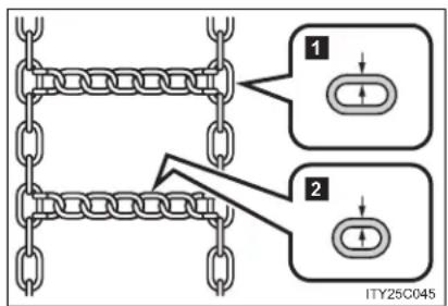
text_image
1 2 ITY25C0451 Side chain
(3.0 mm [0.12 in.] in diameter)
2 Cross chain
(4.0 mm [0.16 in.] in diameter)
Regulations on the use of tire chains
● Regulations regarding the use of tire chains vary according to location and type of road. Always check local regulations before installing chains.
● Install the chains on the front tires.
● Retighten the chains after driving 0.5 - 1.0 km (1/4 - 1/2 mile).
Tire chains
Observe the following precautions when installing and removing chains.
• Install and remove tire chains in a safe location.
- Install tire chains on the front tires only. Do not install the chains on the rear tires.
- Install tire chains following the instructions provided in the accompanying manual.

CAUTION
- Driving with snow tires
Observe the following precautions to reduce the risk of accidents.
Failing to do so may result in a loss of vehicle control and cause death or serious injury.
- Use tires of the size specified for your vehicle.
- Maintain the recommended level of tire inflation pressure.
- Do not drive at speeds in excess of the speed limit or the speed limit specified for the snow tires being used.
- Snow tires should be installed on all wheels.
- Driving with tire chains
Observe the following precautions to reduce the risk of accidents.
Failing to do so may result in the vehicle being unable to be driven safely, and may cause death or serious injury.
- Do not drive in excess of the speed limit specified for the tire chains being used or 50 km/h (30 mph), whichever is lower.
- Avoid driving on bumpy road surfaces or over potholes.
- Avoid sudden turns and braking, as use of chains may adversely affect vehicle handling.
- Slow down sufficiently before entering a curve to ensure that vehicle control is maintained.
2-5. Driving information
Trailer towing
The strain of towing a trailer will have a negative impact on the running performance, handling, fuel consumption and endurance of your vehicle. Use the vehicle features in the correct manner and operate the vehicle with care for safer driving and optimal comfort. Damage and/or malfunctions that occur as a result of towing performed for commercial purposes are not covered by the Toyota warranty.
Ask your local authorized Toyota dealer or repairer, or another duly qualified and equipped professional, for further details before towing, as there are additional legal requirements in some countries.
Weight limits
Check the allowable towing capacity, GVM (Gross Vehicle Mass), MPAC (Maximum Permissible Axle Capacity), and permissible drawbar load before towing. (→P. 720)
■ Towing hitch/bracket
Toyota recommends the use of the Toyota hitch/bracket for your vehicle. Other products of a suitable nature and comparable quality may also be used.
■ To prevent an accident
The handling of the vehicle will feel different when towing a trailer. Beware of the 3 most common causes of towing-related accidents: driver error, excessive speed, and overloading.
Important points regarding trailer loads
■ Total trailer weight and permissible drawbar load
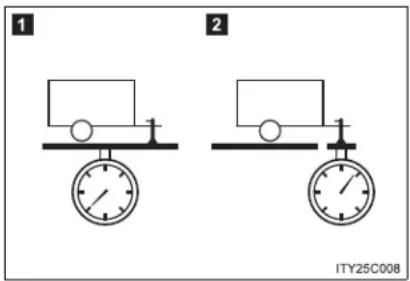
text_image
1 2 ITY25C0081 Total trailer weight
Weight of the trailer itself plus the trailer load should be within the maximum towing capacity. Exceeding this weight is dangerous. (→P. 720)
When the total trailer weight is greater than the vehicle weight, we recommend the use of a friction stabilizer (sway control device).
2 Permissible drawbar load
Allocate the trailer load so that the drawbar load is greater than 25 kg (55.1 lb.) or 4% of the towing capacity. Do not let the drawbar load exceed the indicated weight. (→P. 720)
Information tag (manufacturer's label)
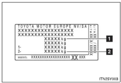
text_image
TOYOTA MOTOR EUROPE NV/SA XXXXXXXXXXXXXXXXXX XXXXXXXXXXXXXXXXXX XXXXX kg XXXXX kg 1- XXXXXX kg 2- XXXXXX kg MODEL XXXXXXXXXXXXXXXXX XX XXX ITN25Y0031 Gross vehicle mass
The combined weight of the driver, passengers, towing hitch, total curb mass and drawbar load should not exceed the gross vehicle mass by more than 100 kg (220.5 lb.). Exceeding this weight is dangerous.
2 Maximum permissible rear axle capacity
The weight borne by the rear axle should not exceed the maximum permissible axle capacity by 15% or more. Exceeding this weight is dangerous.
The values for towing capacity were derived from testing conducted at sea level. Take note that engine output and towing capacity will be reduced at high altitudes.

CAUTION
■ When the gross vehicle mass limit or maximum permissible axle capacity is exceeded
Do not exceed the established speed limit for towing a trailer in built-up areas or 80 km/h (50 mph), whichever is the lower.
Installation positions for the towing hitch/bracket and hitch ball

text_image
1 2 3 4 5 6 ITN25Y0011 460.5 mm (18.1 in.)
2 460.5 mm (18.1 in.)
3 460.5 mm (18.1 in.)
4 460.5 mm (18.1 in.)
5 460.5 mm (18.1 in.)
6 460.5 mm (18.1 in.)
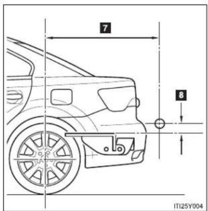
text_image
7 8 IT125Y0047 Sedan: 1111.1 mm (43.7 in.) Wagon: 1175.5 mm (46.2 in.)
8 36.2 mm (1.4 in.)
Tire information
- Ensure that your vehicle's tires are properly inflated. (→P. 739)
- Increase the air pressure of the trailer tires in accordance with the total trailer weight and according to the values recommended by the manufacturer of your trailer.
Trailer lights
Check that the turn signal lights and stoplights are operating correctly every time you hitch up the trailer. Directly wiring up to your vehicle may damage the electrical system and stop the lights from functioning correctly.
■ Break-in schedule
Toyota recommends that vehicles fitted with new power train components should not be used for towing trailers for the first 800 km (500 miles).
Maintenance
- Maintenance must be performed more frequently when using the vehicle for towing due to the greater weight burden placed on the vehicle compared to normal driving.
- Retighten all bolts securing the hitching ball and bracket after towing for approximately 1000 km (600 miles).
■ Safety checks before towing
- Check that the maximum load limit for the towing hitch/bracket and hitch ball is not exceeded. Bear in mind that the coupling weight of the trailer will add to the load exerted on the vehicle. Also make sure that you will not be towing a load that exceeds the maximum permissible axle capacity.
- Ensure that the trailer load is secure.
- Supplementary outside rear view mirrors should be added to the vehicle if the traffic behind cannot be clearly seen with standard mirrors. Adjust the extending arms of these mirrors on both sides of the vehicle so that they always provide maximum visibility of the road behind.
NOTICE
When the rear bumper strengthening material is aluminum
Ensure the steel bracket part does not come directly in contact with that area.
When steel and aluminum come into contact, there is a reaction similar to corrosion, which will weaken the section concerned which may result in damage. Apply a rust inhibitor to parts that will come in contact when attaching a steel bracket.
Guidance
Your vehicle will handle differently when towing a trailer. In order to avoid accident, death or serious injury, keep the following in mind when towing:
- Checking connections between trailer and lights
Stop the vehicle and check the operation of the connection between the trailer and lights after driving for a brief period as well as before setting off.
■ Practicing driving with a coupled trailer
- Get the feel for turning, stopping and reversing with the trailer coupled by practicing in an area with no or light traffic.
- When reversing with a coupled trailer, hold the section of the steering wheel nearest to you and rotate clockwise to turn the trailer left or counterclockwise to turn right. Always rotate gradually to prevent steering error. Have someone guide you when reversing to lessen the risk of accident.
■ Increasing vehicle-to-vehicle distance
At a speed of 10 km/h (6 mph), the distance to the vehicle running ahead of you should be equivalent to or greater than the combined length of your vehicle and trailer. Avoid sudden braking that may cause skidding. Otherwise, the vehicle may spin out of control. This is especially true when driving on wet or slippery road surfaces.
■ Sudden acceleration/steering input/cornering
Executing sharp turns when towing may result in the trailer colliding with your vehicle. Decelerate well in advance when approaching turns and take them slowly and carefully to avoid sudden braking.
■ Important points regarding turning
The wheels of the trailer will travel closer to the inside of the curve than the wheels of the vehicle. To make allowance for this, take the turns wider than you would normally.
■ Important points regarding stability
Vehicle movement resulting from uneven road surfaces and strong crosswinds will affect handling. The vehicle may also be rocked by passing buses or large trucks. Frequently check behind when moving alongside such vehicles. As soon as such vehicle movement occurs, immediately start to decelerate smoothly by slowly applying the brakes. Always steer the vehicle straight ahead while braking.
■ Passing other vehicles
Consider the total combined length of your vehicle and trailer, and ensure that the vehicle-to-vehicle distance is sufficient before executing lane changes.
2-5. Driving information
■ Transmission information
▶ Multidrive or automatic transmission
To maintain engine braking efficiency, when using engine braking, do not use the transmission in "D". Select an appropriate gear in "M" mode.
▶ Manual transmission
To maintain engine braking efficiency, when using engine braking, do not use the transmission in "6".
If the engine overheats...
Towing a loaded trailer up a long steep incline in temperatures exceeding 30^ C ( 85^ F) may result in the engine overheating. If the engine coolant temperature gauge indicates that the engine is overheating, turn the air conditioning off immediately, leave the road and stop the vehicle in a safe place. ( P. 710)
■ When parking the vehicle
Always place wheel chocks under the wheels of both the vehicle and trailer. Firmly set the parking brake and shift the shift lever to "P" for Multidrive or automatic transmission, and "1" or "R" for manual transmission.

CAUTION
■ Vehicle speed in towing
Observe the legal maximum speeds for trailer towing.
■ Before descending hills or long declines
Reduce speed and downshift. However, never downshift suddenly while descending steep or long downhill grades.
Operation of the brake
Do not hold the brake pedal depressed often or for long periods.
Doing so may result in the brake overheating or reduce braking effects.
3-1. Using the air conditioning system and defogger
Automatic air
conditioning system ..... 360
Manual air
conditioning system ..... 370
Power heater 378
Rear window and
outside rear view
mirror defoggers ...... 381
Windshield wiper
de-icer 382
Interior features
3
3-2. Using the audio system
Audio system types ..... 383
Using the radio 391
Using the CD player ..... 398
Playing back MP3 and WMA discs.... 406
Operating an iPod...... 416
Operating a USB memory.... 426
Optimal use of the audio system 436
Using the AUX port...... 438
Using the steering wheel audio switches..... 439
Bluetooth® audio/phone.... 442
Using the Bluetooth ^® audio/phone.... 449
Operating a Bluetooth ^® enabled portable player.... 455
Making a phone call...... 459
Using the "SET UP" menu ("Bluetooth" menu)...... 465
Using the "SET UP" menu ("TEL" menu) ..... 471
3-3. Using the interior lights
Interior lights list...... 478
• Personal/interior light main switch.... 479
• Personal/interior lights .... 479
• Personal lights 480
3-4. Using the storage features
List of storage features ..... 481
- Glove box 482
- Console box...... 483
• Overhead console ..... 484
• Cup holders 485
• Bottle holders...... 486
- Coin box 488
3-5. Other interior features
Sunvisors 489
Vanity mirror 490
Ashtray 491
Cigarette lighter 492
Power outlet...... 493
Seat heaters 494
Armrest 496
Trunk/luggage compartment storage extension .... 497
Panoramic roof shade (wagon)...... 498
Rear sunshade (sedan) 501
Rear side sunshades (sedan) 502
Floor mats.... 503
Trunk features (sedan) ..... 505
Luggage compartment features (wagon)...... 507
3-1. Using the air conditioning system and defogger Automatic air conditioning system\*
Airflow and outlets are automatically adjusted according to the temperature setting.
▶ Vehicles with power heater
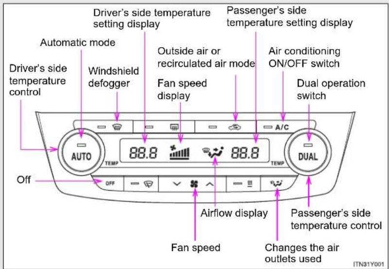
text_image
Driver's side temperature setting display Automatic mode Windshield defogger Driver's side temperature control 88.8 88.8 Fan speed display Passenger's side temperature setting display Outside air or recirculated air mode Fan speed display Air conditioning ON/OFF switch Dual operation switch A/C AUTO TEMP TEMP DUAL Off OFF Airflow display Fan speed Changes the air outlets used ITN31Y001The above illustration is for a left-hand drive vehicle. The button positions are reversed for right-hand drive vehicles.
*: If equipped
▶ Vehicles without power heater

text_image
Driver's side temperature setting display Passenger's side temperature setting display Automatic mode Windshield defogger Outside air or recirculated air mode Air conditioning ON/OFF switch Fan speed display Dual operation switch Driver's side temperature control 88.8 88.8 A/C AUTO TEMP TEMP DUAL Off A OFF Fan speed Changes the air outlets used Airflow display Passenger's side temperature control ITN31Y003A Vehicles with windshield wiper de-icer
B Vehicles without windshield wiper de-icer
The above illustration is for a left-hand drive vehicle. The button positions are reversed for right-hand drive vehicles.
3-1. Using the air conditioning system and defogger
Using the automatic mode
STEP 1 Press

The air conditioning system will begin to operate. Air outlets and fan speed are automatically adjusted according to the temperature setting.
STEP 2 Turning

turning

driver's side.
The temperature for the driver's and front passenger's seats can be set separately.
Adjusting the settings
■ Adjusting the temperature setting
Turning to the right increases the temperature and turning
AUTO to the left decreases the temperature on the driver's side.
The air conditioning system switches between dual and simultaneous modes each time is pressed.
Turning to the right increases the temperature and turning to the left decreases the temperature on the passenger's side.

Operating the passenger's side temperature control will enter dual mode.
Dual mode (the indicator on ☐ on): The temperature for the driver's seat and front passenger's seat can be adjusted separately.
Simultaneous mode (the indicator on is off): Only can be used to adjust the temperature for all seats.
Press “∨” (decrease) or “∧” (increase) on √ * ∧ .
The fan speed is shown on the display. (7 levels)
Press or off to turn the fan off.
3-1. Using the air conditioning system and defogger
■ Changing the air outlets
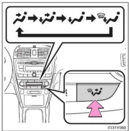
text_image
IT131Y060Press or .
The air outlets switch each time the button is pressed.
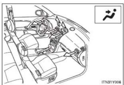
natural_image
Line drawing of a car interior showing steering wheel, dashboard, and seatbelt with no visible text or symbolsAir flows to the upper body.
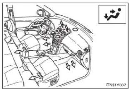
natural_image
Interior view of a car showing steering wheel, dashboard, and seatbelt components (no text or symbols visible)Air flows to the upper body and feet.
3-1. Using the air conditioning system and defogger

text_image
IT131Y063Mainly air flows to the feet.

natural_image
Interior view of a car dashboard with steering wheel, air vent, and directional arrows (no text or symbols)Air flows to the feet and the windshield defogger operates.
■ Switching between outside air and recirculated air modes
Press -
The mode switches between outside air mode (indicator off) and recirculated air mode (indicator on) each time the button is pressed.
3-1. Using the air conditioning system and defogger
Defogging the windshield
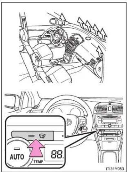
text_image
AUTO TEMP 88. IT131Y053Press
The air conditioning system control operates automatically.
If the outside temperature is 5^ C ( 41^ F) or below, recirculated air mode will automatically switch to outside air mode.
Adjusting the position and opening and closing the air outlets
▶ Center outlets

text_image
2 1 2 1 2 IT31Y0541 Direct air flow to the left or right, up or down.
2 Turn the knob to open or close the vent.
▶ Right and left side outlets

text_image
Diagram showing car interior with labeled parts and directional arrows, likely indicating airflow or traffic flow in a vehicle.1 Direct air flow to the left or right, up or down.
2 Turn the knob to open or close the vent.
■ Using the automatic mode
Fan speed is adjusted automatically in accordance with the temperature setting and ambient conditions. As a result, the following may occur.
- Immediately after is pressed, the fan may stop for a while until warm or cool air is ready to flow.
- Cool air may flow to the area around the upper body when the heater is on.
■ Using the system in recirculated air mode
The windows will fog up more easily if the recirculated air mode is used for an extended period.
■ Switching between outside air and recirculated air modes
Recirculated air mode or outside air mode may be automatically switched to in accordance with the temperature setting and the inside temperature.
■ Window defogger feature
Recirculated air mode may automatically switch to outside air mode in situations where the windows need to be defogged.
■ When outside temperature approaches 0°C (32°F)
The air conditioning system may not operate even when =A/C is pressed.
■ When √ is selected for the air outlets used
For your driving comfort, air flowing to the feet may be warmer than air flowing to the upper body depending on the position of the temperature control dial.
3-1. Using the air conditioning system and defogger
Air conditioning odors
- During use, various odors from inside and outside the vehicle may enter into and accumulate in the air conditioning system. This may then cause odor to be emitted from the vents.
- To reduce potential odors from occurring:
- It is recommended that the air conditioning system be set to outside air mode prior to turning the vehicle off.
- The start timing of the blower may be delayed for a short period of time immediately after the air conditioning system is started in AUTO mode.

CAUTION
■ To prevent the windshield from fogging up
Do not use during cool air operation in extremely humid weather.
The difference between the temperature of the outside air and that of the windshield can cause the outer surface of the windshield to fog up, blocking your vision.

NOTICE
■ To prevent battery discharge
Do not leave the air conditioning system on longer than necessary when the engine is stopped.
3-1. Using the air conditioning system and defogger Manual air conditioning system\*
▶ Vehicles with power heater

text_image
Fan speed display Windshield defogger Fan speed control Temperature setting display Air conditioning ON/OFF switch* Outside air or recirculated air mode Temperature control A/C TEMP TEMP On/off ON/OFF Airflow display Changes the air outlets used ITN31Y002*: If equipped
▶ Vehicles without power heater

text_image
Fan speed display Windshield defogger Fan speed control Temperature setting display Air conditioning ON/OFF switch* Outside air or recirculated air mode Temperature control A/C TEMP TEMP Off A OFF Airflow display Changes the air outlets used B On/off ON/OFF ITN31Y004A Vehicles with windshield wiper de-icer
B Vehicles without windshield wiper de-icer
*:This switch is also installed on vehicles that do not have an air conditioning system. Even though the switch indicator will start to blink when the button is pressed, no system will operate.
Adjusting the settings
■ Adjusting the temperature setting (vehicles with air conditioning system)
Turn the temperature control dial clockwise (warm) or counterclockwise (cool).
If is not pressed, the system will blow ambient temperature air or heated air.
■ Adjusting the temperature setting (vehicles without air conditioning system)
Turn the temperature control dial clockwise (warm) or counterclockwise (cool).
This system will supply only ambient temperature air if the dial is turned to counterclockwise (cool).
Turn the fan speed control dial clockwise (increase) or counterclockwise.
Press, or to turn the fan off.
■ Selecting the air outlets

text_image
IT131Y060Press or .
The air outlets switch each time the button is pressed.
3-1. Using the air conditioning system and defogger
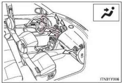
natural_image
Interior view of a car showing dashboard, steering wheel, and seatbelt mechanism (no text or symbols)Air flows to the upper body.
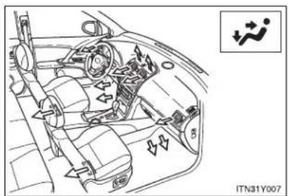
natural_image
Interior view of a car showing dashboard, steering wheel, and air vent (no text or symbols)Air flows to the upper body and feet.
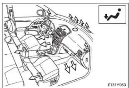
text_image
IT131Y063Mainly air flows to the feet.

natural_image
Interior view of a car dashboard with steering wheel, air vent, and directional arrows (no text or symbols)Air flows to the feet and the windshield defogger operates.
3-1. Using the air conditioning system and defogger
■ Switching between outside air and recirculated air modes
Press =
The mode switches between outside air mode (indicator off) and recirculated air mode (indicator on) each time the button is pressed.
Defogging the windshield
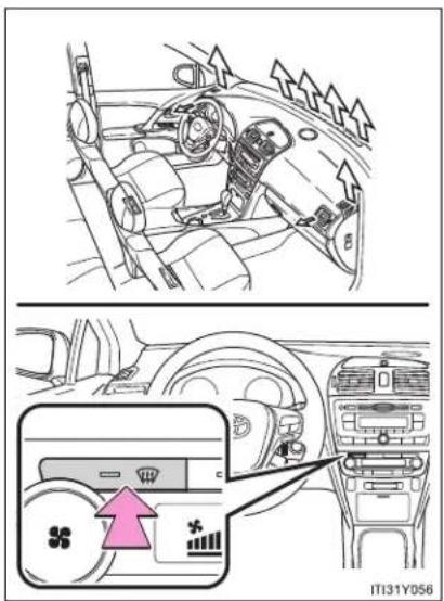
text_image
Diagram showing car interior and dashboard airflow indicators with a highlighted air conditioner unit panelPress
Recirculated air mode will automatically switch to outside air mode.
Adjusting the position of and opening and closing the air outlets
▶ Center outlets
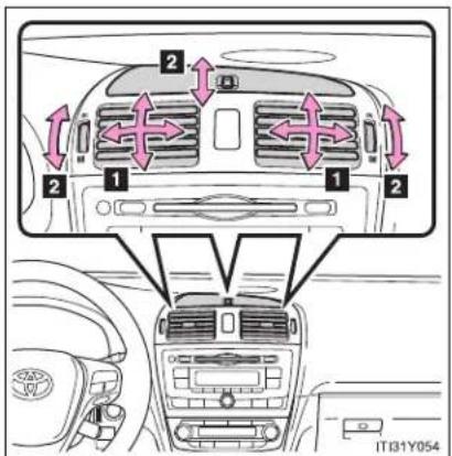
text_image
2 1 2 1 2 IT31Y0541 Direct air flow to the left or right, up or down.
2 Turn the knob up to open the vent and down to close the vent.
▶ Right and left side outlets
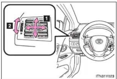
text_image
Diagram showing car interior with labeled parts and directional arrows, likely indicating airflow or traffic flow in a vehicle.1 Direct air flow to the left or right, up or down.
2 Turn the knob up to open the vent and down to close the vent.
■ Using the system in recirculated air mode
The windows will fog up more easily if the recirculated air mode is used for an extended period.
■ When outside air temperature approaches 0^ C ( 32^ F) (vehicles with air conditioning system)
The air conditioning system may not operate even when -is pressed.
■ When ↗ is selected for the air outlets used
For your driving comfort, air flowing to the feet may be warmer than air flowing to the upper body depending on the position of the temperature control dial.
Air conditioning odors
- During use, various odors from inside and outside the vehicle may enter into and accumulate in the air conditioning system. This may then cause odor to be emitted from the vents.
- To reduce potential odors from occurring: It is recommended that the air conditioning system be set to outside air mode prior to turning the vehicle off.

CAUTION
■ To prevent the windshield from fogging up
Do not use 📄 during cool air operation in extremely humid weather. The difference between the temperature of the outside air and that of the windshield can cause the outer surface of the windshield to fog up, blocking your vision.

NOTICE
■ To prevent battery discharge
Do not leave the air conditioning system on longer than necessary when the engine is stopped.
3-1. Using the air conditioning system and defogger Power heater\*
This feature is used to keep the cab warm in cold conditions.
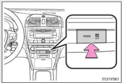
text_image
一环 IT31Y061On/off
The power heater turns on about 30 seconds after you press the switch and it takes about another 55 seconds to warm up.
■ Power heater can be operated when
The engine is running.
• The outside temperature is low.
The engine coolant temperature is low.
■ Normal characteristics of power heater operation
The following cases do not indicate a malfunction.
- When the power heater is turned on or off, some white smoke and a slight odor may be emitted from the power heater exhaust that is located under the floor.
- When the power heater is being used under extremely cold conditions, vapor may be visible from its exhaust.
- When the power heater is turned off, you may hear a sound in the engine compartment for about 2 minutes until the power heater turns off completely.
*: If equipped
3-1. Using the air conditioning system and defogger
■ After the heater is off
We recommend not restarting the heater for 10 minutes after you turn it off. Otherwise, a noise may be heard as the heater ignites.
■ When refueling your vehicle
The engine must be turned OFF. Turning the engine OFF turns the power heater off.

CAUTION
■ To prevent burns or damage on your vehicle
natural_image
Line drawing of a car's front grille with a cartoon character on the roof (no text or symbols)- Do not touch the heater or its exhaust pipe as they are hot. You may burn yourself.
- Keep flammable items such as fue away from the heater and its exhaust pipe. This may cause a fire.

NOTICE
■ To prevent damage to your vehicle
- Do not turn the heater on and off repeatedly in 5 minute intervals as this can shorten the life of the heater components. If the engine must be turned on and off repeatedly within short intervals (such as when the vehicle is being used for delivery purposes), turn the heater off.
- Do not modify or open the heater without consulting any authorized Toyota dealer or repairer, or another duly qualified and equipped professional. This may cause a heater malfunction or a fire.
- Be careful not to splash water or spill liquid directly on the heater or on the heater fuel pump. This may cause the heater to malfunction.
- Keep the intake and exhaust pipes of the heater free from water, snow, ice, mud, etc. If the pipes become clogged, this can cause the heater to malfunction.
- If you notice anything unusual, such as a fluid leak, smoke or poor operation, turn off the heater and have your vehicle checked by any authorized Toyota dealer or repairer, or another duly qualified and equipped professional.
3-1. Using the air conditioning system and defogger Rear window and outside rear view mirror defoggers
Clear the rear window using the defogger. (Turning the rear window defogger on will turn the outside rear view mirror defoggers on. The outside rear view mirror is used to remove raindrops, dew and frost from the outside rear view mirrors.)
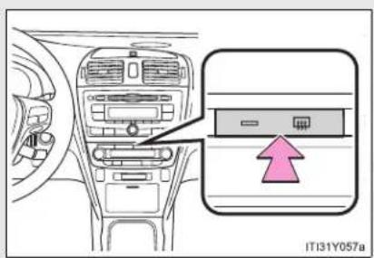
text_image
IT131Y057aOn/off
The defoggers will automatically turn off after approximately 15 minutes. Pressing the switch again also turns the rear window defogger off.
The rear window and outside rear view mirror defoggers can be operated when
▶ Vehicles with smart entry & start system
The "ENGINE START STOP" switch is in IGNITION ON mode.
▶ Vehicles without smart entry & start system
The engine switch is in the "ON" position.

CAUTION
When the outside rear view mirror defoggers are on
Do not touch the rear view mirror surfaces, as they can become very hot and burn you.
3-1. Using the air conditioning system and defogger Windshield wiper de-icer\*
This feature is used to prevent ice from building up on the wind-shield and wiper blades.

text_image
IT131Y059On/off
The windshield wiper de-icer will automatically turn off after approximately 15 minutes. Pressing the switch again also turns the de-icer off.
The windshield wiper de-icer can be operated when
▶ Vehicles with smart entry & start system
The "ENGINE START STOP" switch is in IGNITION ON mode.
▶ Vehicles without smart entry & start system
The engine switch is in the "ON" position.
CAUTION
■ When the windshield wiper de-icer is on
Do not touch the glass at the lower part of the windshield or to the side of the front pillars as the surfaces can become very hot and burn you.
*: If equipped
3-2. Using the audio system
Audio system types\*
▶ Vehicles with a "touch screen"
Owners of models equipped with a "touch screen" should refer to the "touch screen" Owner's Manual".
For the below items, refer to the according page.
● Using a USB port: →P. 426
● Using an AUX port: →P. 438
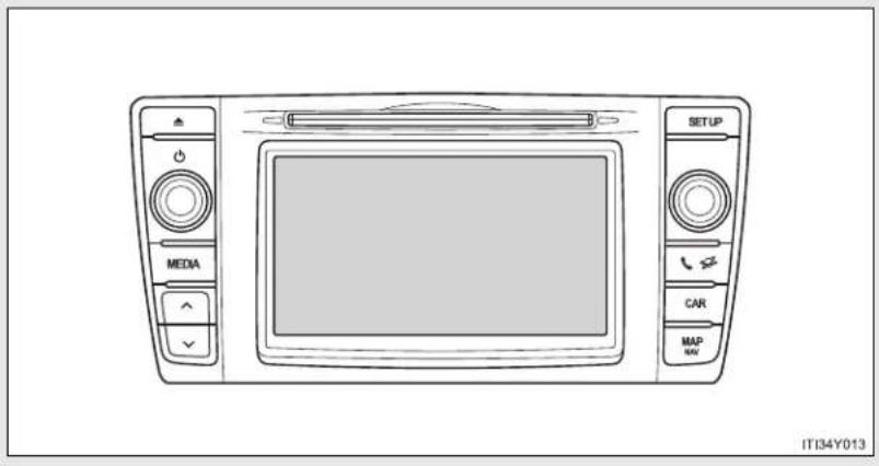
text_image
MEDIA SETUP CAR MAP NAV IT34Y013*: If equipped
3-2. Using the audio system
▶ Vehicles without a "touch screen" CD player and AM/FM radio
Type A
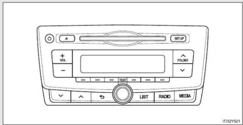
text_image
SETUP + VOL - FOLDER - TEXT LIST RADIO MEDIA IT32Y021Type B

text_image
SETUP + VOL - = = = = TEXT = = = = LIST RADIO MEDIA IT32Y022Type C

text_image
SETUP + VOL - LIST SCAN TEXT RADIO MEDIA IT32Y0233-2. Using the audio system
| Title Page | |
| Using the radio P. 391 | |
| Using the CD player P. 398 | |
| Playing back MP3 and WMA discs P. 406 | |
| Operating an iPod P. 416 | |
| Operating a USB memory P. 426 | |
| Optimal use of the audio system P. 436 | |
| Using the AUX port P. 438 | |
| Using the steering wheel audio switches P. 439 |
■ Using cellular phones
Interference may be heard through the audio system's speakers if a cellular phone is being used inside or close to the vehicle while the audio system is operating.
■ Certification for the Bluetooth®(vehicles with a "touch screen")
Panasonic Corporation Automotive Systems Company
4261 Ikonobe-Cho, Tsuzuki-Ku, Yokohama 224-8520 Japan
DECLARATION of CONFORMITY
We, Panasonic Corporation Automotive Systems Company
4261 Ikonobe-cho, Tsuzuki-ku, Yokohama-shi, Kanagawa 224-8520 Japan
declare under our sole responsibility that the product:
Product : Bluetooth Module Assy
Model/Type: YEAP01A046 / YEAP01A049 / YEAP01A112
to which this declaration relates is in conformity with the essential requirements and other relevant requirements of the R&TTE Directive (1999/5/EC).
The product is in conformity with the following standards:
RADIO : EN 300 328 V1.7.1: 2006-10
EMC : EN 301 489-1 V1.8.1: 2008-04
EN 301 489-3 V1.4.1: 2002-08
EN 301 489-17 V2.1.1: 2009-05
SAFETY : EN 60950-1: 2006 + Amd.11: 2009

Date : August 24, 2010
Signature : K. Jezai
Name : Kimito Terai
Title : Staff Engineer
3-2. Using the audio system
| Hereby, Panasonic Corporation Automotive Systems Company, declares that this YEAP01A046 / YEAP01A049 / YEAP01A112 is in compliance with the essential requirements and other relevant provisions of Directive 1999/5/EC. |
| Panasonic Corporation Automotive Systems Company vakuuttaa täten että YEAP01A046 / YEAP01A049 / YEAP01A112 typpinen laite on direktiivin 1999/5/EY oleellisten vaatimusten ja sitä koskevien direktiivin muiden ehtojen mukainen. |
| Hierbij verklaart Panasonic Corporation Automotive Systems Company dat het toestel YEAP01A046 / YEAP01A049 / YEAP01A112 in overeenstemming is met de essentiële eisen en de andere relevante bepalingen van richtlijn 1999/5/EG. |
| Par la présente Panasonic Corporation Automotive Systems Company déclare que l'appareil YEAP01A046 / YEAP01A049 / YEAP01A112 est conforme aux exigences essentielles et aux autres dispositions pertinentes de la directive 1999/5/CE. |
| Härmed intygar Panasonic Corporation Automotive Systems Company att denna YEAP01A046 / YEAP01A049 / YEAP01A112 står i överensstämmelse med de väsentliga egenskapskrav och övriga relevanta bestämmelser som framgår av direktiv 1999/5/EG. |
| Undertegnede Panasonic Corporation Automotive Systems Company erklærer herved, at følgende udstyr YEAP01A046 / YEAP01A049 / YEAP01A112 overholder de väsentlige krav og øvrige relevante krav i direktiv 1999/5/EF. |
| Hiermit erklärt Panasonic Corporation Automotive Systems Company, dass sich das Gerät YEAP01A046 / YEAP01A049 / YEAP01A112 in Übereinstimmung mit den grundlegenden Anforderungen und den übrigen einschlägigen Bestimmungen der Richtlinie 1999/5/EG befindet. |
| ME THN ΠΑΡΟΥΣΑ Panasonic Corporation Automotive Systems Company ΔΗΛΩΝΕΙ OTI YEAP01A046 / YEAP01A049 / YEAP01A112 ΣΥΜΜΟΡΦΩΝΕΤΑΙ ΠΡΟΣ ΤΙΣ ΟΥΣΙΩΔΕΙΣ ΑΠΑΙΤΗΣΕΙΣ ΚΑΙ ΤΙΣ ΛΟΙΠΕΣ ΣΧΕΤΙΚΕΣ ΔΙΑΤΑΞΕΙΣ ΤΗΣ ΟΔΗΓΙΑΣ 1999/5/EK. |
| Con la presente Panasonic Corporation Automotive Systems Company dichiara che questo YEAP01A046 / YEAP01A049 / YEAP01A112 è conforme ai requisiti essenziali ed alle altre disposizioni pertinenti stabilite dalla direttiva 1999/5/CE. |
| Por medio de la presente Panasonic Corporation Automotive Systems Company declara que el YEAP01A046 / YEAP01A049 / YEAP01A112 cumple con los requisitos esenciales y cualesquiera otras disposiciones aplicables o exigibles de la Directiva 1999/5/CE. |
| Panasonic Corporation Automotive Systems Company declara que este YEAP01A046 / YEAP01A049 / YEAP01A112 está conforme com os requisitos essenciais e outras disposições da Directiva 1999/5/CE. |
| Hawnhekk, Panasonic Corporation Automotive Systems Company, jiddikjara li dan YEAP01A046 / YEAP01A049 / YEAP01A112 jikkonforma mal-ħtiġijiet essenzjali u ma provvedimenti oħrajn relevanti li hemm fid-Dirrettiva 1999/5/EC. |
| Käesolevaga kinnitab Panasonic Corporation Automotive Systems Company seadme YEAP01A046 / YEAP01A049 / YEAP01A112 vastavust direktivi 1999/5/EÜ põhinõuetele ja nimetatud direktiivist tulenevatele teistele asjakohastele sätetele. |
| Alulírott, Panasonic Corporation Automotive Systems Company nyilatkozom, hogy a YEAP01A046 / YEAP01A049 / YEAP01A112 megfelel a vonatkozó alapvető követelményeknek és az 1999/5/EC irányelv egyéb előírásainak. |
| Panasonic Corporation Automotive Systems Company týmto vyhlasuje, že YEAP01A046 / YEAP01A049 / YEAP01A112 splňa základné požiadavky a všetky príslušné ustanovenia Smernice 1999/5/ES. |
| Panasonic Corporation Automotive Systems Company tímto prohlašuje, že tento YEAP01A046 / YEAP01A049 / YEAP01A112 je ve shodě se základními požadavky a dalšími příslušnými ustanoveními směrnice 1999/5/ES. |
| Panasonic Corporation Automotive Systems Company izjavlja, da je ta YEAP01A046 / YEAP01A049 / YEAP01A112 v skladu z bistvenimi zahtevami in ostalimi relevantními določili direktive 1999/5/ES. |
| Šiuo Panasonic Corporation Automotive Systems Company deklaruoja, kad šis YEAP01A046 / YEAP01A049 / YEAP01A112 atitinka esminius reikalavimus ir kitas 1999/5/EB Direktyvos nuostatas. |
| Ar šo Panasonic Corporation Automotive Systems Company deklarē, ka YEAP01A046 / YEAP01A049 / YEAP01A112 atbiist Direktīvas 1999/5/EK būtiskajām prasībām un citiem ar to saistītajiem noteikumiem. |
| Niniejszym Panasonic Corporation Automotive Systems Company oświadcza, že YEAP01A046 / YEAP01A049 / YEAP01A112 jest zgodny z zasadniczymi wymogami oraz pozostałymi stosownymi postanowieniami Dyrektywy 1999/5/EC. |
| Hér með lýsir Panasonic Corporation Automotive Systems Company yfir því að YEAP01A046 / YEAP01A049 / YEAP01A112 er í samræmi við grunnkröfur og aðrar kröfur, sem gerðar eru í tilskipun 1999/5/EC. |
| Panasonic Corporation Automotive Systems Company erklærer herved at utsyret YEAP01A046 / YEAP01A049 / YEAP01A112 er i samsvar med de grunnleggende krav og øvrige relevante krav i direktiv 1999/5/EF. |
| Ovim, Panasonic Corporation Automotive Systems Company, izjavljuje da ovaj YEAP01A046 / YEAP01A049 / YEAP01A112 je usklađen sa bitnim zahtjevima i drugim relevantnim odredbama Direktive 1999/5/EC. |
■ About Bluetooth®(vehicles with a "touch screen")

Bluetooth®
Bluetooth is a registered trademark of Bluetooth SIG. Inc.

NOTICE
■ To prevent battery discharge
Do not leave the audio system on longer than necessary when the engine is stopped.
■ To avoid damaging the audio system
Take care not to spill drinks or other fluids over the audio system.
3-2. Using the audio system
Using the radio\*
▶ Type A

text_image
Power Station selector AF/region code/TA mode setup SETUP Volume FM (○) RADIO TP AF CD IN FOLDER - TEXT LIST RADIO MEDIA Back button Seeking the frequency Displays station list Adjusting the frequency or selecting items AM/FM mode button IT32Y026*: If equipped
3-2. Using the audio system
▶ Type B

text_image
Power Station selector AF/region code/TA mode setup SETUP Volume FM RADIO TP AF REG COIN 1 2 3 4 5 6 TEXT LIST RADIO MEDIA Back button Displayst station list Adjusting the frequency or selecting items AM/FM mode button Seeking the frequency▶ Type C

text_image
Power Station selector AF/region code/TA mode setup SETUP Volume FM RADIO TP AF REQ SPIN LIST SCAN TEXT RADIO MEDIA AM/FM mode button Scanning for receivable stations Adjusting the frequency or selecting items/displays station list Seeking the frequencySetting station presets
STEP 1 Search for desired stations by turning or pressing

STEP 2 Press and hold the button (from [1] to [6]) the station is to be set to until you hear a beep.
Scanning radio stations (type C only)
■ Scanning the preset radio stations
STEP 1 Press and hold until you hear a beep. STEP 2 When the desired station is reached, press again.
■ Scanning all radio stations within range
STEP 1 Press SCAN
All stations with reception will be played for 5 seconds each.
STEP 2 When the desired station is reached, press again.
Using the station list
■ Updating the station list
STEP 1 Press (type A and B) or (type C)

The station list will be displayed.
STEP 2 Press [UPDATE] to update the list.
"Updating" is displayed while the searching is in process, and then available stations will be listed on the display.
To cancel the updating process, press (type A and B) or [BACK] (type C).
■ Selecting a station from the station list
STEP 1 Press (type A and B) or (type C)

The station list will be displayed.
STEP 2 Turn (to select a station.
STEP 3 Press to tune in the station.
To return to the previous display, press (type A and B) or [BACK] (type C).
RDS (Radio Data System)
This feature allows your radio to receive station.
■ Listening to stations of the same network
STEP 1 Press SETUP.

text_image
STEP 2 Turn to "RADIO" and press .STEP 3 Turn as corresponds to the desired mode: "FM AF" or "Region code".
STEP 4 Press to select "ON" or "OFF".
FM AF ON mode: The station among those of the same network with strong reception is selected.
Region code ON mode: The station among those of the same network with strong reception and broadcasting the same program is selected.
3-2. Using the audio system
■ Traffic information
STEP 1 Press SETUP.

text_image
STEP 2 Turn to "RADIO" and press .

text_image
STEP 4 Press to select "ON" or "OFF".TP mode: The system automatically switches to traffic information when a broadcast with a traffic information signal is received.
The station returns to the previous one when the traffic information ends.
TA mode: The system automatically switches to traffic information when a broadcast with a traffic information signal is received. In FM modes, the system will be mute unless traffic information is being broadcast.
The audio system returns to the previous mode when the traffic information ends.
■ EON (Enhanced Other Network) system (for traffic announcement function)
If the RDS station (with EON data) you are listening to is not broadcasting a traffic information program and the audio system is in the TA (traffic announcement) mode, the radio will be switched automatically to a station broadcasting a traffic information program in the EON AF list when traffic information begins.
■ When the battery is disconnected
Stations presets are erased.
■ Reception sensitivity
- Maintaining perfect radio reception at all times is difficult due to the continually changing position of the antenna, differences in signal strength and surrounding objects, such as trains, transmitters, etc.
- Sedan: The radio antenna is mounted inside the rear window. To maintain clear radio reception, do not attach metallic window tinting or other metallic objects to the antenna wire mounted inside the rear window.
- Wagon: The radio antennas are mounted inside the rear quarter window and on the rear roof. To maintain clear radio reception, do not attach metallic window tinting or other metallic objects to the antenna wire mounted inside the rear quarter window. The rear roof antenna can be removed from the base by turning.
■ Digital Audio Broadcast (DAB) radio
The optional radio antenna and tuner are necessary for the use of Digital Audio Broadcast (DAB) radio.
3-2. Using the audio system
Using the CD player\*
▶ Type A
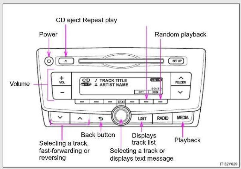
text_image
CD eject Repeat play Power Random playback Volume + VOL CD TRACK TITLE ARTIST NAME CD IN 50:33 FOLDER - BPT RDM TEXT LIST RADIO MEDIA Back button Selecting a track, fast-forwarding or reversing Displays track list Selecting a track or displays text message Playback IT132Y029*: If equipped
▶ Type B
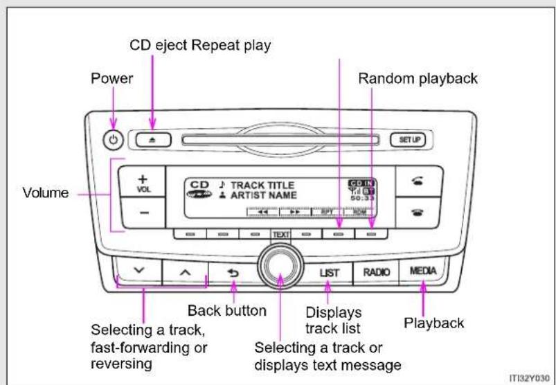
text_image
CD eject Repeat play Power Random playback SETUP Volume + VOL CD TRACK TITLE ARTIST NAME 50:33 - TEXT LIST RADIO MEDIA Back button Selecting a track, fast-forwarding or reversing Displays track list Selecting a track or displays text message Playback IT32Y030▶ Type C
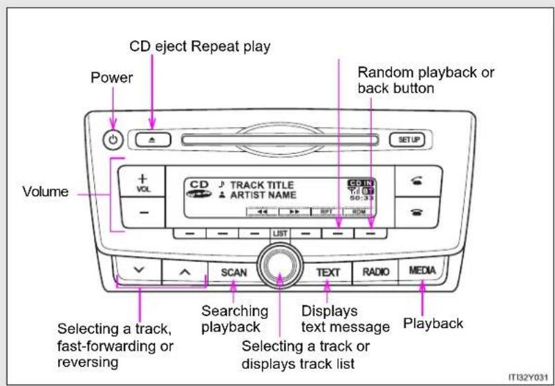
text_image
CD eject Repeat play Power Volume + VOL CD TRACK TITLE ARTIST NAME CDIN 50:33 SETUP LIST SCAN Text RADIO MEDIA Selecting a track, fast-forwarding or reversing Searching playback Selecting a track or displays track list Displays text message Playback IT32Y0313-2. Using the audio system
Loading CDs
Insert a CD.
Ejecting CDs
Press and remove the CD.
Selecting a track
Turn or press to move up or to move down
until the desired track number is displayed.
Selecting a track from a track list
STEP 1 Press (type A and B) or (type C).
The track list will be displayed.
STEP 2 Turn and press to select a track.
To return to the previous display, press (type A
and B), or BACK.
Scanning track (type C only)
STEP 1 Press SCAN
The first 10 seconds of each track will be played.
To cancel, press again.
STEP 2 Press again when the desired track is reached.
Fast-forwarding and reversing tracks
To fast-forward or reverse, press and hold


Random playback
Press —
[RDM].
To cancel, press [RDM] again.
Repeat play
Press
[RPT].
To cancel, press [RPT] again.
Switching the display
Press (type A and B) or (type C). TEXT
Track title, Artist name and CD title are shown on the display.
To return to the previous display, press Ⓞ or [type A and B), TEXT or [BACK] (type C).
Display
Up to 24 characters can be displayed.
Depending on the contents recorded, the characters may not be displayed properly or may not be displayed at all.
Error messages
"ERROR": This indicates a problem either in the CD or inside the player.
"CD CHECK": The CD may be dirty, damaged or inserted up-side down.
"WAIT": Operation has stopped due to a high temperature inside the
player. Wait for a while and then press .Mthe CD still cannot be played back, contact any authorized Toyota dealer or repairer, or another duly qualified and equipped professional.
■ Discs that can be used
Discs with the marks shown below can be used.
Playback may not be possible depending on recording format or disc features, or due to scratches, dirt or deterioration.


CDs with copy-protect features may not play correctly.
■ CD player protection feature
To protect the internal components, playback is automatically stopped when a problem is detected while the CD player is being used.
If a CD is left inside the CD player or in the ejected position for extended periods
The CD may be damaged and may not play properly.
Lens cleaners
Do not use lens cleaners. Doing so may damage the CD player.

CAUTION
■ Certification for the CD player
This product is a class I laser product.
A laser beam leak may result in hazardous radiation exposure.
- Do not open the cover of the player or attempt to repair the unit by yourself.
Refer servicing to qualified personnel.
- Laser power: No hazardous

NOTICE
■ CDs and adapters that cannot be used
Do not use the following types of CDs, 8 cm (3 in.) CD adapters or Dual Disc.
Doing so may damage the player and/or the CD insert/eject function.

natural_image
Illustration of three metallic discs with a red prohibition symbol (no text or labels)• CDs that have a diameter that is not 12 cm (4.7 in.)
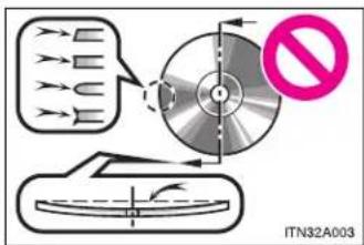
text_image
ITN32A003Low-quality and deformed CDs
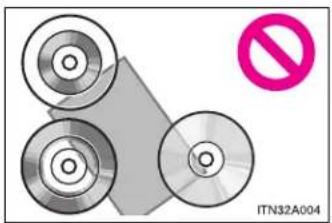
natural_image
Diagram showing three circular components and a diagonal line with a pink prohibition symbol (no text or labels on components)• CDs with a transparent or translucent recording area
text_image
ITN32A005- CDs that have tape, stickers or CD-R labels attached to them, or that have had the label peeled off

NOTICE
■ CD player precautions
Failure to follow the precautions below may result in serious damage to the CDs or the player itself.
- Do not insert anything other than CDs into the CD slot.
- Do not apply oil to the CD player.
- Store CDs away from direct sunlight.
- Never try to disassemble any part of the CD player.
3-2. Using the audio system
Playing back MP3 and WMA discs\*
▶ Type A
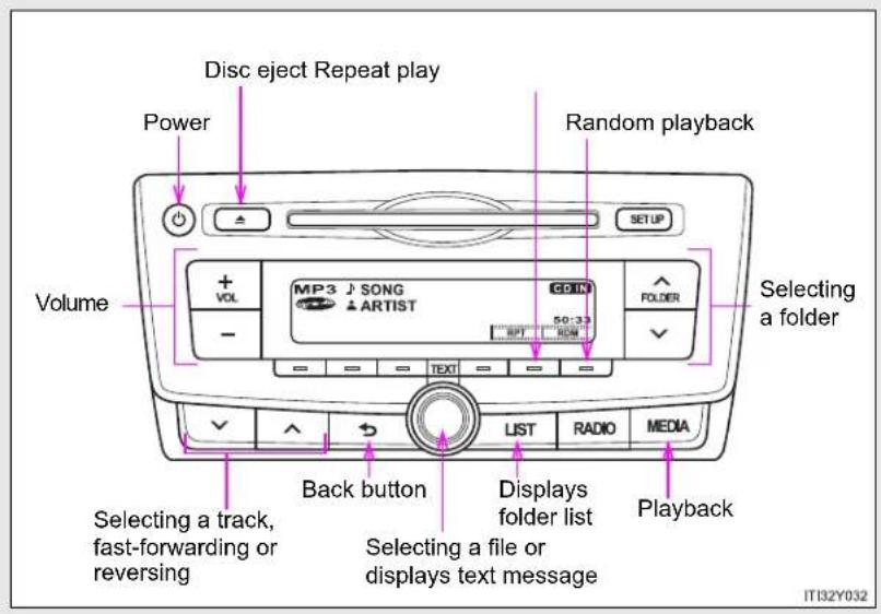
text_image
Disc eject Repeat play Power Random playback Volume Selecting a folder MP3 SONG ARTIST CDIN FOLDER 50:33 LIST RADIO MEDIA Back button Selecting a track, fast-forwarding or reversing Selecting a file or displays text message Playback IT132Y032*: If equipped
▶ Type B
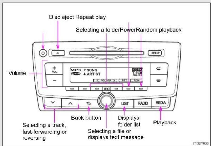
text_image
Disc eject Repeat play Selecting a folderPowerRandom playback Volume + VOL MP3 SONG - ARTIST SETUP Back button Selecting a track, fast-forwarding or reversing List RADIO MEDIA Displays folder list Selecting a file or displays text message Playback IT32Y033▶ Type C

text_image
Disc eject Repeat play Selecting a folderPowerRandom playback Volume + VOL MP3 J SONG - ARTIST CDN - LIST - RPM 50:33 SCAN TEXT RADIO MEDIA Selecting a track, fast-forwarding or reversing Searching playback Selecting a file or displays folder list Displays text message Playback IT32Y034Loading and ejecting MP3 and WMA discs
→P. 398
Selecting a folder
■ Selecting folders one at a time
Press or (type A), √ [<] or [>] (type

B and C) to select the desired folder.
■ Selecting a folder and file from folder list
STEP 1 Press (type A and B) or (type C

The folder list will be displayed.
STEP 2 Turn and press to select a folder and a file.
To return to the previous display, press (type A and B) or [BACK] (type C).
To exit, press (type A and B) or (type C).
■ Returning to the first folder
Press and hold (type A) or [<] (type-B and C) until you hear a beep.
Scanning a folder (type C only)
STEP 1 Press and hold until you hear a beep.
The first 10 seconds of the first file in each folder will be played.
STEP 2 When the desired folder is reached, press again.
Selecting files
Turn or press or to select the desired file.
Scanning the files in a folder (type C only)
STEP 1 Press SCAN
The first 10 seconds of each file will be played.
STEP 2 When the desired file is reached, press once again.
Fast-forwarding and reversing files
To fast-forward or reverse, press and hold


3-2. Using the audio system
Random playback
Pressing [RDM] changes modes in the following order:
Folder random→Disc random→Off
Repeat play
Pressing [RPT] changes modes in the following order:
File repeat→Folder repeat*→Off
*: Available except when RDM (random playback) is selected
Switching the display
Press

and B) or
(type
C). TEXT
Track title, Artist name and Album title (MP3 only) are shown on the display.
To return to the previous display, press (or type A and B),
or or[BACK] (type C).
■ Display
→P. 402
Error messages
"ERROR": This indicates a problem either in the CD or inside the player.
"CD CHECK": The CD may be dirty, damaged or inserted up-side down.
"NO SUPPORT": This indicates that the MP3/WMA file is not included in the CD.
■ Discs that can be used
Discs with the marks shown below can be used.
Playback may not be possible depending on recording format or disc features, or due to scratches, dirt or deterioration.

■ CD player protection feature
To protect the internal components, playback is automatically stopped when a problem is detected while the CD player is being used.
If a CD is left inside the CD player or in the ejected position for extended periods
The CD may be damaged and may not play properly.
Lens cleaners
Do not use lens cleaners. Doing so may damage the CD player.
3-2. Using the audio system
MP3 and WMA files
MP3 (MPEG Audio LAYER3) is a standard audio compression format.
Files can be compressed to approximately 1/10 of their original size by using MP3 compression.
WMA (Windows Media Audio) is a Microsoft audio compression format.
This format compresses audio data to a size smaller than that of the MP3 format.
There is a limit to the MP3 and WMA file standards and to the media/formats recorded by them that can be used.
- MP3 file compatibility
- Compatible standards MP3 (MPEG1 LAYER3, MPEG2 LSF LAYER3)
- Compatible sampling frequencies MPEG1 LAYER3: 32, 44.1, 48 (kHz) MPEG2 LSF LAYER3: 16, 22.05, 24 (kHz)
- Compatible bit rates (compatible with VBR) MPEG1 LAYER3: 64, 80, 96, 112, 128, 160, 192, 224, 256, 320 (kbps)
- MPEG2 LSF LAYER3: 64, 80, 96, 112, 128, 144, 160 (kbps)
- Compatible channel modes: stereo, joint stereo, dual channel and monaural
WMA file compatibility
- Compatible standards WMA Ver. 7, 8, 9
- Compatible sampling frequencies 32, 44.1, 48 (kHz)
- Compatible bit rates (only compatible with 2-channel playback) Ver. 7, 8: CBR 48, 64, 80, 96, 128, 160, 192 (kbps) Ver. 9: CBR 48, 64, 80, 96, 128, 160, 192, 256, 320 (kbps)
- Compatible media
Media that can be used for MP3 and WMA playback are CD-Rs and CD-RWs.
Playback in some instances may not be possible, depending on the status of the CD-R or CD-RW. Playback may not be possible or the audio may jump if the disc is scratched or marked with fingerprints.
- Compatible disc formats
The following disc formats can be used.
• Disc formats: CD-ROM Mode 1 and Mode 2
CD-ROM XA Mode 2, Form 1 and Form 2
- File formats: ISO9660 Level 1, Level 2, (Romeo, Joliet)
MP3 and WMA files written in any format other than those listed above may not play correctly, and their file names and folder names may not be displayed correctly.
Items related to standards and limitations are as follows.
• Maximum directory hierarchy: 8 levels
• Maximum length of folder names/file names: 32 characters
• Maximum number of folders: 192 (including the root)
• Maximum number of files per disc: 255
- File names
The only files that can be recognized as MP3/WMA and played are those with the extension .mp3 or .wma.
- Multi-sessions
As the audio system is compatible with multi-sessions, it is possible to play discs that contain MP3 and WMA files. However, only the first session can be played.
3-2. Using the audio system
ID3 and WMA tags
ID3 tags can be added to MP3 files, making it possible to record the track title, artist name, etc.
The system is compatible with ID3 Ver. 1.0, 1.1, and Ver. 2.2, 2.3 ID3 tags. (The number of characters is based on ID3 Ver. 1.0 and 1.1.)
WMA tags can be added to WMA files, making it possible to record the track title and artist name in the same way as with ID3 tags.
• MP3 and WMA playback
When a disc containing MP3 or WMA files is inserted, all files on the disc are first checked. Once the file check is finished, the first MP3 or WMA file is played. To make the file check finish more quickly, we recommend you do not write in any files other than MP3 or WMA files or create any unnecessary folders.
If the discs contain a mixture of music data and MP3 or WMA format data, only music data can be played.
- Extensions
If the file extensions .mp3 and .wma are used for files other than MP3 and WMA files, they will be mistakenly recognized and played as MP3 and WMA files. This may result in large amounts of interference and damage to the speakers.
- Playback
- To play MP3 file with steady sound quality, we recommend a fixed bit rate of 128 kbps and a sampling frequency of 44.1 kHz.
- CD-R or CD-RW playback may not be possible in some instances, depending on the characteristics of the disc.
- There is a wide variety of freeware and other encoding software for MP3 and WMA files on the market, and depending on the status of the encoding and the file format, poor sound quality or noise at the start of playback may result. In some cases, playback may not be possible at all.
- When files other than MP3 or WMA files are recorded on a disc, it may take more time to recognize the disc and in some cases, playback may not be possible at all.
- Microsoft, Windows, and Windows Media are the registered trademarks of Microsoft Corporation in the U.S. and other countries.
NOTICE
■ CDs and adapters that cannot be used ( P. 404)
■ CD player precautions ( P. 405)
3-2. Using the audio system
Operating an iPod\*
Connecting an iPod enables you to enjoy music from the vehicle speakers.
■ Connecting an iPod
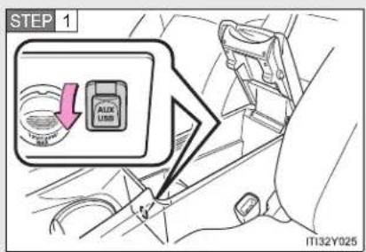
text_image
STEP 1 AUX USB IT132Y025Open the cover and connect an iPod using an iPod cable.
Turn on the power of the iPod if it is not turned on.

Control panel
▶ Type A
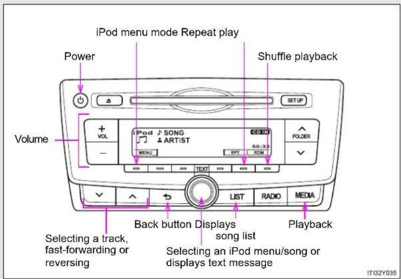
text_image
iPod menu mode Repeat play Power Shuffle playback Volume + VOL iPod SONG ARTIST 50:33 FOLDER - MENU SPT ROM TEXT LIST RADIO MEDIA Back button Displays song list Selecting a track, fast-forwarding or reversing Selecting an iPod menu/song or displays text message Playback IT32Y035*: If equipped
▶ Type B
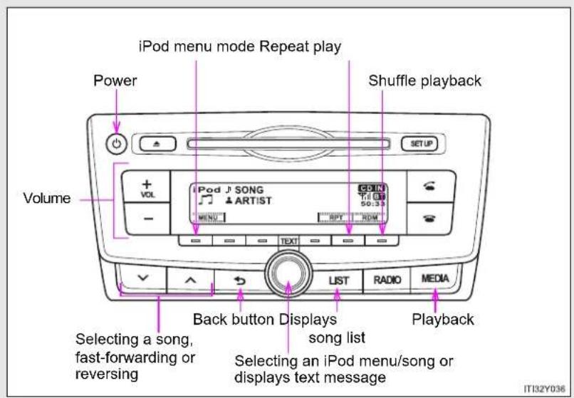
text_image
iPod menu mode Repeat play Power Shuffle playback Volume + VOL iPod J SONG ARTIST CDIN Till 50:39 MENU RPT RDM TEXT LIST RADIO MEDIA Back button Displays song list Selecting a song, fast-forwarding or reversing Selecting an iPod menu/song or displays text message Playback IT132Y036▶ Type C

text_image
iPod menu mode Repeat play Power Shuffle playback or back button Volume + VOL iPod J SONG ARTIST MENU RPT ROM LIST SCAN Text RADIO MEDIA fast-forwarding or reversing Displays text message Selecting an iPod menu/song or displays song list PlaybackSelecting a so3-2. Using the audio system
Selecting a play mode
STEP 1 Press [MENU] to select iPod menu mode.
STEP 2 Turning

clockwise
changes
the play mode in the fol-
lowing order:
"Playlists"→"Artists"→"Albums"→"Songs"→"Podcasts"→"Genres"
→“Composers”→“Audiobooks”
STEP 3 Press

to select the desired play mode.
Play mode list
| Play mode | First selection | Second selection | Third selection | Fourth selection |
| “Playlists” | Playlists select | Songs select | - | - |
| “Artists” Artists | select | Albums select | Songs select | - |
| “Albums” | Albums select | Songs select | - | - |
| “Songs” Songs | select --- | |||
| “Podcasts” | Podcasts select | Episodes select | - | - |
| “Genres” Genre | select Artists | select | Albums select | Songs select |
| “Composers” | Composers select | Albums select | Songs select | - |
| “Audiobooks” | Audiobooks select | Chapter select | - | - |
3
Interior features
3-2. Using the audio system
Selecting a list
STEP 1 Turn to display the first selection list.
STEP 2 Press to select the desired item.
Pressing the knob changes to the second selection list.
STEP 3 Repeat the same procedure to select the desired item.
To return to the previous selection list, press (type A and B) or [BACK] (type C).
Selecting songs
Turn or press or to select the desired song.
Selecting a song from the song list
STEP 1 Press
(type A
and B) or
(type C)

The song list will be displayed.
STEP 2 Turn
to sele
ect a song.
STEP 3 Press
to play the song.
To return to the previous display, press (type A and B) or [BACK] (type C).
Fast-forwarding and reversing songs
Press and hold


Repeat play
Press [RPT].
To cancel, press [RPT] again.
Shuffle playback
Pressing [RDM] changes modes in the following order:
Track shuffle→Album shuffle→Off.
Switching the display
Press

and B) or
(type
C). TEXT
Track title, Artist name and Album title are shown on the display.
To return to the previous display, press

type A and B),
or or[BACK] (type C).
About iPod
- Apple is not responsible for the operation of this device or its compliance with safety and regulatory standards.
- iPod is a trademark of Apple Inc., registered in the U.S. and other countries.
■ iPod functions
- When an iPod is connected and the audio source is changed to iPod mode, the iPod will resume play from the same point in which it was last used.
- Depending on the iPod that is connected to the system, certain functions may not be available. If a function is unavailable due to a malfunction (as opposed to a system specification), disconnecting the device and reconnecting it once again may resolve the problem.
- While connected to the system, the iPod cannot be operated with its own controls. It is necessary to use the controls of the vehicle's audio system instead.
■ iPod problems
To resolve most problems encountered when using your iPod, disconnect your iPod from the vehicle iPod connection and reset it.
For instructions on how to reset your iPod, refer to your iPod Owner's Manual.
Display
→P. 402
Error messages
"ERROR": This indicates a problem in the iPod or its connection.
"NO SONGS": This indicates that there is no music data in the iPod.
"NO PLAYLIST": This indicates that some available songs are not found in a selected playlist.
"UPDATE YOUR iPod": This indicates that the version of the iPod is not compatible. Upgrade your iPod software to the latest version.
- Compatible models
| Model Generation Software version | ||
| iPod 5th generation | Ver. 1.3.0 | |
| iPod nano | 1st generation Ver. 1.3.1 | |
| 2nd generation Ver. 1.1.3 | ||
| 3rd generation Ver. 1.1.3 | ||
| 4th generation Ver. 1.0.4 | ||
| 5th generation Ver. 1.0.2 | ||
| 6th generation Ver. 1.0.0 | ||
| iPod touch | 1st generation Ver. 3.1.3 | |
| 2nd generation | Ver. 3.1.3 | |
| Ver. 4.2.1 | ||
| Late 2009 (8 GB) | Ver. 3.1.3 | |
| Ver. 4.2.1 | ||
| 3rd generation(32 GB/64 GB) | Ver. 3.1.3 | |
| Ver. 4.2.1 | ||
| 4th generation Ver. 4.2.1 | ||
| iPod classic | 1st generation Ver. 1.1.2 | |
| 2nd generation (120 GB) Ver. 2.0.1 | ||
| Late 2009 (160 GB) Ver. 2.0.4 | ||
| iPhone | 1st generation (iPhone) Ver. 3.1.3 | |
| 2nd generation (iPhone 3G) | Ver. 3.1.3 | |
| Ver. 4.2.1 | ||
| 3rd generation(iPhone 3GS) | Ver. 3.1.3 | |
| Ver. 4.2.1 | ||
| 4th generation (iPhone 4) Ver. 4.2.1 | ||
Depending on differences between models or software version etc., some models listed above might be incompatible with this system. iPod 4th generation and earlier models are not compatible with this system. iPod mini, iPod shuffle and iPod photo are not compatible with this system.
Items related to standards and limitations are as follows:
• Maximum number of lists in device: 9999
● Maximum number of songs in device: 65535
● Maximum number of songs per list: 65535

CAUTION
■ Caution while driving
Do not connect iPod or operate the controls. Doing so may cause an accident, resulting in death or serious injury.

NOTICE
■ To prevent damage to iPod
- Do not leave iPod in the vehicle. The temperature inside the vehicle may become high, resulting in damage to the iPod.
- Do not push down on or apply unnecessary pressure to the iPod while it is connected as this may damage the iPod or its terminal.
- Do not insert foreign objects into the port as this may damage the iPod or its terminal.
3-2. Using the audio system
Operating a USB memory\*
Connecting a USB memory enables you to enjoy music from the vehicle speakers.
■ Connecting a USB memory

text_image
STEP 1 AUX USB IT32Y025Open the cover and connect a USB memory.
Turn on the power of the USB memory if it is not turned on.

*: If equipped
Control panel
▶ Type A

text_image
Power Repeat play Random playback Volume USB J SONG ARTIST CD IN FOLDER Selecting a folder Back button Selecting a file, fast-forwarding or reversing Selecting a file or displays text message LIST RADIO MEDIA Playback IT32Y0383-2. Using the audio system
▶ Type B
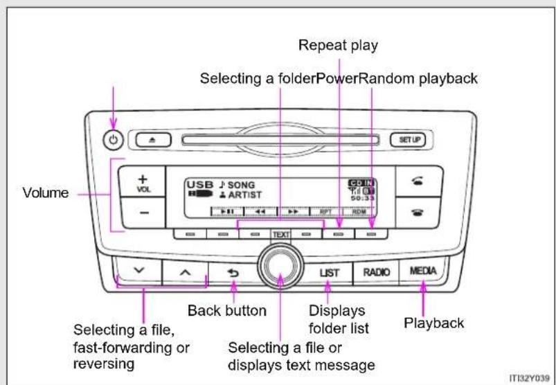
text_image
Repeat play Selecting a folderPowerRandom playback Volume USB SONG ARTIST SETUP + - - USB 50:33 RDT RDM LIST RADIO MEDIA Back button Selecting a file, fast-forwarding or reversing Selecting a file or displays text message Playback IT32Y039▶ Type C
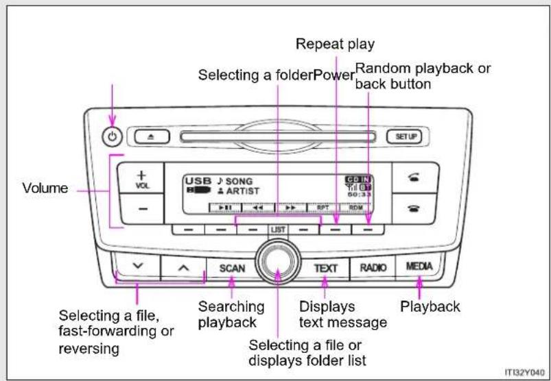
text_image
Repeat play Selecting a folderPower Random playback or back button Volume USB J SONG ARTIST CDIN TIL 01 60:33 LIST RPT RDM SCAN Text RADIO MEDIA Selecting a file, fast-forwarding or reversing Searching playback Displays text message Selecting a file or displays folder list Playback IT32Y040Selecting a folder
■ Selecting folders one at a time
Press or folder (type A), or [<] or [>]
(type B and C) to select the desired folder.
■ Selecting a folder and file from folder list
STEP 1 Press (type A and B) or (type C).
The folder list will be displayed.
STEP 2 Turn and press to select a folder and file.
To return to the previous display, press (type A and B) or [BACK] (type C).
To exit, press (type A and B) or (type C).
Scanning the first file of all the folders (type C only)
STEP 1 Press and hold until you hear a beep. The first 10 seconds of the first file in each folder will be played.
STEP 2 When the desired folder is reached, press again.
3-2. Using the audio system
Selecting files
Turn

ss
or
to
sel
ect
th
e d
esi
red
file
Scanning the files in a folder (type C only)
STEP 1
Press
F
SCAN
The first 10 seconds of each file will be played.
STEP 2
WH
hen
the
e de
esin
ed
file
is
rea
che
ed,
pre
ess
a
gai
Fast-forwarding and reversing files
To fast
-for
wa
rd
or r
eve
erse
e, p
res
s a
nd
ho
d
on
.
1
|
Random playback
Pressing
[RDM]
cha
ang
ges
mo
ode
s in
n th
e fo
ollov
win
g o
rde
er:
Folder ra
ndom→
Dis
c ra
and
om
1→(
Off
Repeat play
Pressing
[RPT]
cha
ng
es
mo
des
s in
the
e fo
llov
vin
g o
rde
er:
File repe
at→Fold
er
rep
eat
* →
.Off
:
[Non-Text]
[Non-Text]
[Non-Text]
[Non-Text]
[Non-Text]
[Non-Text]
[Non-Text]
*: Availab
le except
wh
en
RD
M (
ranc
dom
n pla
ayb
ack
) is
sel
ect
ed
Switching the display
Press

and B) or
(type
C). TEXT
Track title, Artist name and Album title (MP3 only) are shown on the display.
To return to the previous display, press (type A and B) or [BACK] (type C).

USB memory functions
- Depending on the USB memory that is connected to the system, the device itself may not be operable and certain functions may not be available.
If the device is inoperable or a function is unavailable due to a malfunction (as opposed to a system specification), disconnecting the device and reconnecting it once again may resolve the problem. - If the USB memory still does not begin operation after being disconnected and reconnected, format the memory.
■ Display
→P. 402
Error messages
"ERROR": This indicates a problem in the USB memory or its connection.
"NO MUSIC": This indicates that no MP3/WMA files are included in the USB memory.
3-2. Using the audio system
USB memory
- Compatible devices USB memory that can be used for MP3 and WMA playback
-
Compatible device formats The following device formats can be used:
-
USB communication formats: USB2.0 FS (12mbps)
- File formats: FAT16/32 (Windows)
• Correspondence class: Mass storage class
MP3 and WMA files written in any format other than those listed above may not play correctly, and their file names and folder names may not be displayed correctly.
Items related to standards and limitations are as follows:
• Maximum directory hierarchy: 8 levels
• Maximum number of folders in a device: 999 (including the root)
• Maximum number of files in a device: 9999
• Maximum number of files per folder: 255
- MP3 and WMA files
MP3 (MPEG Audio LAYER 3) is a standard audio compression format. Files can be compressed to approximately 1/10 of their original size using MP3 compression.
WMA (Windows Media Audio) is a Microsoft audio compression format. This format compresses audio data to a size smaller than that of the MP3 format.
There is a limit to the MP3 and WMA file standards that can be used and to the media/formats on which the files are recorded.
- MP3 file compatibility
- Compatible standards MP3 (MPEG1 AUDIO LAYERII, III, MPEG2 AUDIO LAYERII, III, MPEG2.5)
- Compatible sampling frequencies MPEG1 AUDIO LAYERII, III: 32, 44.1, 48 (kHz) MPEG2 AUDIO LAYERII, III: 16, 22.05, 24 (kHz) MPEG2.5: 8, 11.025, 12 (kHz)
- Compatible bit rates (compatible with VBR) MPEG1 AUDIO LAYERII, III: 32-320 (kbps) MPEG2 AUDIO LAYERII, III: 32-160 (kbps) MPEG2.5: 32-160 (kbps)
- Compatible channel modes: stereo, joint stereo, dual channel and monaural
WMA file compatibility
- Compatible standards WMA Ver. 9
- Compatible sampling frequencies HIGH PROFILE 32, 44.1, 48 (kHz)
- Compatible bit rates HIGH PROFILE 32-320 (kbps, VBR)
- File names
The only files that can be recognized as MP3/WMA and played are those with the extension .mp3 or .wma.
3-2. Using the audio system
ID3 and WMA tags
ID3 tags can be added to MP3 files, making it possible to record the track title, artist name, etc.
The system is compatible with ID3 Ver. 1.0, 1.1, and Ver. 2.2, 2.3, 2.4 ID3 tags. (The number of characters is based on ID3 Ver. 1.0 and 1.1.)
WMA tags can be added to WMA files, making it possible to record the track title and artist name in the same way as with ID3 tags.
• MP3 and WMA playback
- When a device containing MP3 or WMA files is connected, all files in the USB memory are checked. Once the file check is finished, the first MP3 or WMA file is played. To make the file check finish more quickly, we recommend that you do not include any files other than MP3 or WMA files or create any unnecessary folders.
- When the USB memory is connected and the audio source is changed to USB memory mode, the USB memory will start playing the first file in the first folder.
If the same device is removed and reinserted (and the contents have not been changed), the USB memory will resume play from the same point in which it was last used.
- Extensions
If the file extensions .mp3 and .wma are used for files other than MP3 and WMA files, they will be skipped (not played).
- Playback
- To play MP3 files with steady sound quality, we recommend a fixed bit rate of at least 128 kbps and a sampling frequency of 44.1 kHz.
- There is a wide variety of freeware and other encoding software for MP3 and WMA files on the market, and depending on the status of the encoding and the file format, poor sound quality or noise at the start of playback may result.
In some cases, playback may not be possible at all. - Microsoft, Windows, and Windows Media are registered trademarks of Microsoft Corporation in the U.S.A. and other countries.

CAUTION
■ Caution while driving
Do not connect USB memory or operate the controls. Doing so may cause an accident, resulting in death or serious injury.

NOTICE
■ To prevent damage to USB memory
- Do not leave USB memory in the vehicle. The temperature inside the vehicle may become high, resulting in damage to the USB memory.
- Do not push down on or apply unnecessary pressure to the USB memory while it is connected as this may damage the USB memory or its terminal.
- Do not insert foreign objects into the port as this may damage the USB memory or its terminal.
3-2. Using the audio system
Optimal use of the audio system\*

text_image
1 SETUP 2 3 IT132Y0461 Displays the current mode
2 Changes the following settings
• Sound quality and volume balance ( P. 437)
The sound quality and balance setting can be changed to produce the best sound.
• Automatic sound levelizer on/off ( P. 437)
3 Selecting the mode
Using the audio control function
■ Changing sound quality modes
STEP 1 Press SETUP.
STEP 2 Turn to select "Sound Setting".
STEP 3 Press
STEP 4 Turn (as corresponds to the desired mode.
■ Adjusting sound quality
Turning

adjusts the level.
| Sound quality mode | Mode displayed | Level | Turn to the left | Turn to the right |
| Bass* “BASS” -5 to 5 | Low High | |||
| Treble* “TREBLE” -5 to 5 | ||||
| Front/rear volume balance | “FADER” F7 | to R7 Shifts to rear | rear | Shifts to front |
| Left/right volume balance | “BALANCE” L7 | to R7 Shifts to left | to left | Shifts to right |
*: The sound quality level is adjusted individually in each audio mode.
■ Adjusting the Automatic Sound Levelizer (ASL)
When ASL is selected, turning

right changes the
amount of ASL in the order of LOW, MID and HIGH.
Turning

to the left turns ASL off.
ASL automatically adjusts the volume and tone quality according to vehicle speed.
3-2. Using the audio system
Using the AUX port\*
This port can be used to connect a portable audio device and listen to it through the vehicle's speakers.
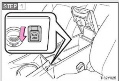
text_image
STEP 1 AUTO USB IT32Y025Open the cover and connect the portable audio device.
STEP 2 Press until "AUX" is displayed.
- Operating portable audio devices connected to the audio system
The volume can be adjusted using the vehicle's audio controls. All other adjustments must be made on the portable audio device itself.
■ When using a portable audio device connected to the power outlet
Noise may occur during playback. Use the power source of the portable audio device.
*: If equipped
3-2. Using the audio system
Using the steering wheel audio switches
Some audio features can be controlled using the switches on the steering wheel.

text_image
1 2 3 MODE ITN32Y0121 Volume
2 Radio mode: Select radio stations
CD mode:
Select tracks and files (MP3 and WMA)
iPod mode: Selects a song USB memory mode:
Selects a file and folder
Bluetooth ^® audio mode (if equipped):
Selects a track and album
3 Power on, select audio source
Turning on the power
Press when the audio system is turned off.
3-2. Using the audio system
Changing the audio source
Press when the audio system is turned on. The audio source
changes as follows each time is pressed. If a mode cannot be used, it will be skipped.
AM→FM→CD mode→iPod or USB memory→Bluetooth® audio*→AUX
*: If equipped
Adjusting the volume
Press “+” on to increase the volume and “-” to decrease the volume.
Hold down "+" or "-" on to continue increasing or decreasing the volume.
Silencing a sound
Press and hold

To cancel, press and hold

Selecting a radio station
STEP 1 Press to select the radio mode.
STEP 2 Press “^” or “√” on ▼ to select a preset station.
To scan for receivable stations, press and hold “^” or “√” on until you hear a beep.

Selecting a track/file or song
STEP 1 Press to select CD, iPod or USB memory, Bluetooth audio mode.
STEP 2 Press “^” or “√” on √ to select the desired track/file or song.
Selecting an album
STEP 1 Press to select the Bluetooth ^ audio mode.
STEP 2 Press and hold “^” or “∨” on √ √ √ until you hear a beep.
Selecting a folder (MP3 and WMA or USB memory)
STEP 1 Press to select CD or USB memory mode.
STEP 2 Press and hold “^” or “√” on √ √ √ until you hear a beep.
CAUTION
■ To reduce the risk of an accident
Exercise care when operating the audio switches on the steering wheel.
3-2. Using the audio system
Bluetooth® audio/phone\*
Bluetooth® audio
The Bluetooth ^® audio system enables you to enjoy music played on a portable digital audio player (portable player) from the vehicle speakers via wireless communication.
This audio system supports Bluetooth ^® , a wireless data system capable of playing portable audio music without cables. If your portable player does not support Bluetooth ^® , the Bluetooth ^® audio system will not function.
Bluetooth® phone (hands-free phone system)
This system supports Bluetooth ^® , which allows you to make or receive calls without using cables to connect a cellular phone and the system, and without operating the cellular phone.
*: If equipped
■ Conditions affecting operation
The Bluetooth ^® audio/phone may not operate normally in the following situations:
The portable player does not support Bluetooth®
● The cellular phone is located outside the service area
The Bluetooth device is switched off
The Bluetooth device has a low battery
- The Bluetooth device is not connected to the system
- The Bluetooth device is behind the seat or in the glove box or console box, or metal material covers or touches the device
■ When transferring ownership of the vehicle
Be sure to initialize the system to prevent personal data from being improperly accessed. ( P. 470)
About Bluetooth®

text_image
Bluetooth® ITN33A005Bluetooth is a registered trademark of Bluetooth SIG. Inc.
3-2. Using the audio system
■ Compatible models
- Bluetooth®specifications:
Ver. 1.1, or higher (recommended: Ver. 2.1 + EDR or higher)
- Following Profiles:
- A2DP (Advanced Audio Distribution Profile) Ver. 1.0, or higher (recommended: Ver. 1.2 or higher)
- AVRCP (Audio/Video Remote Control Profile) Ver. 1.0 or higher (recommended: Ver. 1.3 or higher)
Portable players must correspond to the above specifications in order to be connected to the Bluetooth ^® audio system. However, please note that some functions may be limited depending on the type of portable player.
Cellular phone
- HFP (Hands Free Profile) Ver. 1.0 or higher (Recommended: Ver. 1.5)
• OPP (Object Push Profile) Ver. 1.1
• PBAP (Phone Book Access Profile) Ver. 1.0
Certification
Panasonic Corporation
Automotive Systems Company
4261 Ikonobe-cho, Tsuzuki-ku, Yokohama City 224-8520, Japan
DECLARATION of CONFORMITY
We, Panasonic Corporation, Automotive Systems Company of the above address, hereby declare, at our sole responsibility that the following product conforms to the Essential Requirements of the Radio and Telecommunications Terminal Equipment Directive 1999/5/EC in accordance with the tests conducted to the appropriate requirements of the relevant standards, as listed herewith.
Product: Bluetooth module Assy
Model/ Type Number: YEP0PTA184
Directive and Standards used: Radio: EN300 328 V1.7.1: 2006-10
EMC: EN301 489-1 V1.8.1: 2008-04
EN301 489-17 V2.1.1: 2008-04
LVD: EN60950-1: 2006 + Amd.11: 2009
Year of affixing CE marking: 2011
CE
Date : March 7, 2011
3-2. Using the audio system
| Hereby, Panasonic Corporation Automotive Systems Company, declares that this YEP0PTA184 is in compliance with the essential requirements and other relevant provisions of Directive 1999/5/EC. |
| Panasonic Corporation Automotive Systems Company vakuuttaa täten että YEP0PTA184 typpinen laite on direktiivin 1999/5/EY oleellisten vaatimusten ja sitä koskevien direktiivin muiden ehtojen mukainen. |
| Hierbij verklaart Panasonic Corporation Automotive Systems Company dat het toestel YEP0PTA184 in overeenstemming is met de essentiële eisen en de andere relevante bepalingen van richtlijn 1999/5/EG. |
| Par la présente Panasonic Corporation Automotive Systems Company déclare que l'appareil YEP0PTA184 est conforme aux exigences essentielles et aux autres dispositions pertinentes de la directive 1999/5/CE. |
| Härmed intygar Panasonic Corporation Automotive Systems Company att denna YEP0PTA184 står I överensstämmelse med de väsentliga egenskapskrav och övriga relevanta bestämmelser som framgår av direktiv 1999/5/EG. |
| Undertegnede Panasonic Corporation Automotive Systems Company erklærer herved, at fölgende udstyr YEP0PTA184 overholder de väsentlige krav og øvrige relevante krav i direktiv 1999/5/EF. |
| Hiermit erklärt Panasonic Corporation Automotive Systems Company, dass sich das Gerät YEP0PTA184 in Übereinstimmung mit den grundlegenden Anforderungen und den übrigen einschlägigen Bestimmungen der Richtlinie 1999/5/EG befindet. |
| ME THN ΠΑΡΟΥΣΑ Panasonic Corporation Automotive Systems Company ΔΗΛΩΝΕΙ OTI YEP0PTA184 ΣΥΜΜΟΡΦΩΝΕΤΑΙ ΠΡΟΣ ΤΙΣ ΟΥΣΙΩΔΕΙΣ ΑΠΑΙΤΗΣΕΙΣ ΚΑΙ ΤΙΣ ΛΟΙΠΕΣ ΣΧΕΤΙΚΕΣ ΔΙΑΤΑΞΕΙΣ ΤΗΣ ΟΔΗΓΙΑΣ 1999/5/EK. |
| Con la presente Panasonic Corporation Automotive Systems Company dichiara che questo YEP0PTA184 è conforme ai requisiti essenziali ed alle altre disposizioni pertinenti stabilite dalla direttiva 1999/5/CE. |
| Por medio de la presente Panasonic Corporation Automotive Systems Company declara que el YEP0PTA184 cumple con los requisitos esenciales y cualesquiera otras disposiciones aplicables o exigibles de la Directiva 1999/5/CE. |
| Panasonic Corporation Automotive Systems Company declara que este YEP0PTA184 está conforme com os requisitos essenciais e outras disposições da Directiva 1999/5/CE. |
| Hawnhekk, Panasonic Corporation Automotive Systems Company, jiddikjara li dan YEP0PTA184-jikkonforma mal-ħtiġijiet essenzjali u ma provvedimenti oħrajn relevanti li hemm fid-Dirrettiva 1999/5/EC. |
| Käesolevaga kinnitab Panasonic Corporation Automotive Systems Company seadme YEP0PTA184 vastavust direktiivi 1999/5/EÜ põhinõuetele ja nimetatud direktiivist tulenevatele teistele asjakohastele sätetele. |
| Alulírott, Panasonic Corporation Automotive Systems Company nyilatkozom, hogy a YEP0PTA184 megfelel a vonatkozó alapvetõ követelményeknek és az 1999/5/EC irányelv egyéb előírásainak. |
| Panasonic Corporation Automotive Systems Company týmto vyhlasuje, že YEP0PTA184 splňa základné požiadavky a všetky príslušné ustanovenia Smernice 1999/5/ES. |
| Panasonic Corporation Automotive Systems Company tímto prohlašuje, že tento YEP0PTA184 je ve shodě se základními požadavky a dalšími příslušnými ustanoveními směrnice 1999/5/ES. |
| Panasonic Corporation Automotive Systems Company izjavlja, da je ta YEP0PTA184 v skladu z bistvenimi zahtevami in ostalimi relevantnimi določili direktive 1999/5/ES. |
| Šiuo Panasonic Corporation Automotive Systems Company deklaruoja, kad šis YEP0PTA184 atitinka esminius reikalavimus ir kitas 1999/5/EB Direktyvos nuostatas. |
| Ar šo Panasonic Corporation Automotive Systems Company deklarě, ka YEP0PTA184 atbilst Direktīvas 1999/5/EK būtiskajām prasībām un citiem ar to saistītajiem noteikumiem. |
| Niniejszym Panasonic Corporation Automotive Systems Company oświadcza, že YEP0PTA184 jest zgodny z zasadniczymi wymogami oraz pozostałymi stosownymi postanowieniami Dyrektywy 1999/5/EC. |
| Hér með lýsir Panasonic Corporation Automotive Systems Company yfir því að YEP0PTA184 er í samræmi við grunnkröfur og aðrar kröfur, sem gerðar eru í tilskipun 1999/5/EC. |
| Panasonic Corporation Automotive Systems Company erklærer herved at utsyret YEP0PTA184 er i samsvar med de grunnleggende krav og øvrige relevante krav í direktiv 1999/5/EF. |
| Ovim, Panasonic Corporation Automotive Systems Company, izjavljuje da ovaj YEP0PTA184 je usklađen sa bitnim zahtjevima i drugim relevantnim odredbama Direktive 1999/5/EC. |
3-2. Using the audio system

CAUTION
■ Caution while driving
Observe the following precautions to avoid an accident that could result in death or serious injuries.
- Do not use a cellular phone.
- Do not connect Bluetooth device or operate the controls.

NOTICE
To prevent damage to Bluetooth device
Do not leave Bluetooth ^® device in the vehicle. The temperature inside the vehicle may become high, resulting in damage to the device.
3-2. Using the audio system
Using the Bluetooth® audio/phone\*
Audio unit
▶ Type A
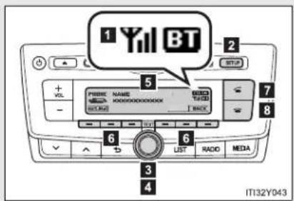
text_image
1 Yil BT 2 3 4 5 6 7 8 9 LIST RADIO MEDIA IT132Y0431 Bluetooth® connection condition
If "BT" is not displayed, the Bluetooth® audio/phone cannot be used.
2 Displays set up menu
3 Selects items such as menu and number
Turn: Selects an item
Press: Inputs the selected item
4 Displays information that is too long to be displayed at one time on the display (press and hold)
5 Display
A message, name, number, etc. is displayed.
Lower-case characters and special characters cannot be displayed.
6 Selects speed dials
7 Off-hook switch
Turns the hands-free system on/starts a call
8 On-hook switch
Turns the hands-free system off/ends a call/refuses a call
▶ Type B

text_image
1 Yil BT 2 3 4 5 6 7 8 9 10 11 12 13 14 SCAN TEXT AUDIO MEDIA IT132Y0441 Bluetooth® connection condition
If "BT" is not displayed, the Bluetooth® audio/phone cannot be used.
2 Displays set up menu
3 Selects items such as menu and number
Turn: Selects an item
Press: Inputs the selected item
4 Displays information that is too long to be displayed at one time on the display (press and hold)
5 Display
A message, name, number, etc. is displayed.
Lower-case characters and special characters cannot be displayed.
6 Selects speed dials
7 Off-hook switch
Turns the hands-free system on/starts a call
8 On-hook switch
Turns the hands-free system off/ends a call/refuses a call
■ Steering wheel switches (Bluetooth® audio)
→P. 439
■ Steering wheel switches (Bluetooth® phone)
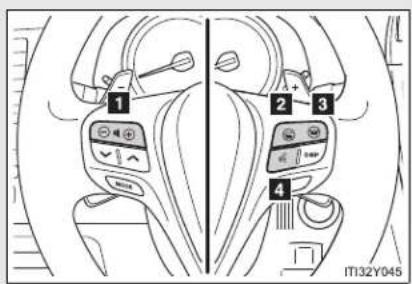
text_image
1 2 3 4 IT132Y0451 Volume
The call volume can be adjusted using this button.
2 Off-hook switch
Turns the hands-free sys- tem on/starts a call
3 On-hook switch
Turns the hands-free system off/ends a call/refuses a call
4 Talk switch
Turns the voice command system on (press)/turns the voice command system off (press and hold)
Microphone
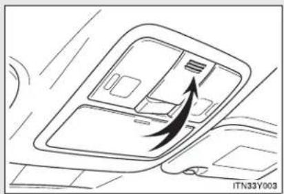
natural_image
Diagram of a car interior showing airflow or traffic flow with an arrow pointing to a device (no text or symbols present)Using the Bluetooth® audio/phone for the first time
Before using the Bluetooth ^® audio/phone, it is necessary to register a Bluetooth ^® device in the system. Follow the procedure below to register (pair) a device:
STEP 1 Press and select "Bluetooth" using .

STEP 2 Press and select "Pairing" using .

A passkey will be displayed.
STEP 3 SSP (Secure Simple Pairing) incompatible Bluetooth® devices: Input the passkey into the device.
SSP (Secure Simple Pairing) compatible Bluetooth ^® devices: Select "Yes" to register the device. Depending on the type of device, it may register automatically.
If a Bluetooth ^® device has both music player and cellular phone functions, both functions will be registered at the same time. When deleting the device, both functions will be deleted at the same time.
If the off-hook switch, talk switch or is pressed and the "TEL"
mode is entered when no phones have been registered, the registration screen will be automatically displayed.
Menu list of the Bluetooth® audio/phone
| First menu S | Second menu Third menu Operation details | ||
| “Bluetooth” | “Pairing” - | Registering a Bluetooth® device | |
| “List Phone” - | Listing the registered cellular phones | ||
| “List Audio” - | Listing the registered portable players | ||
| “Passkey” - | Changing the pass-key | ||
| “BT Power” - | Setting automatic connection of the device on or off | ||
| “Bluetooth info” | “Device Name” “Device Address” | Displaying the device status | |
| “Display setting” - | Setting the automatic connection confirmation display to on or off | ||
| “Initialize” - | Initializing the settings | ||
3
Interior features
3-2. Using the audio system
| First menu S | Second menu Third menu Operation details | ||
| “TEL” | “Phonebook” | “Add contacts” Adding a new number | |
| “Add SD” | Registering a speed dial | ||
| “Delete Call History” | Deleting a number stored in the call history | ||
| “Delete contacts” | Deleting a number stored in the phone-book | ||
| “Delete other PB” | Deleting a phone-book's data | ||
| “HF Sound Setting” | “Call Volume” Setting call volume | ||
| “Ring tone Volume” | Setting ring tone volume | ||
| “Ring tone” Setting the ring tone | |||
| “Transfer Histories” | - | Transferring the call histories | |
Bluetoothaudio/phone system functions
Depending on the Bluetooth ^® device, certain functions may not be available.
3-2. Using the audio system
Operating a Bluetooth® enabled portable player\*
▶ Type A

text_image
Power Playback/pause Repeat play Random playback Volume BTA SONG ARTIST CDIN Till OUT 50:33 LIST RADIO MEDIA Back button Selecting a track, fast-forwarding or reversing Selecting a track or displays text message IT132Y041*: If equipped
3-2. Using the audio system
▶ Type B

text_image
Power Playback/pause Repeat play Random playback or back button Volume + VOLT BTA SONG ARTIST CDIN 50:33 LIST SCAN Text RADIO MEDIA Selecting a track, fast-forwarding or reversing Displays text message Selecting a track Playback IT132Y042Selecting and scanning an album
■ Selecting an album
Pres = () ◦ ( )=to select the desired album.
■ Scanning the first track of all the album (type B only)
STEP 1 Press and hold until you hear a beep.
The first 10 seconds of the first track in each album will be played.
STEP 2 When the desired album is reached, press again.
Selecting and scanning tracks
- Selecting a track
Press or to select the desired track.
■ Scanning the tracks in an album (type B only)
STEP 1 Press SCAN
The first 10 seconds of each track will be played.
STEP 2 When the desired track is reached, press again.
Fast-forwarding and reversing tracks
Press and hold orv.
Repeat play
Pressing [RPT] changes modes in the following order: Track repeat→Album repeat→Off.
3-2. Using the audio system
Random playback
Pressing [RDM] changes modes in the following order:
Album random→All track random→Off.
Playing and pausing tracks
Press


( ).
Switching the display
Press

or
(type
B). TEXT
Track title and Artist name are displayed on the display.
To return to the previous display, press

or (type A) or

or
[BACK] (type B).
Bluetoothaudio system functions
Depending on the portable player that is connected to the system, certain functions may not be available.
3-2. Using the audio system
Making a phone call\*
To enter the "TEL" mode, press or the off-hook switch.
■ Making a phone call
● Dialing by selecting a name
- Speed dialing
● Dialing by entering the number
- Dialing from call histories
■ Receiving a phone call
- Answering the phone
- Refusing the call
Operations during a call
- Transferring a call
- Muting your voice
- Inputting digits
- Setting call volume
■ Adjusting the ring tone volume when receiving a call
*: If equipped
Dialing by selecting a name
STEP 1 Select "Phonebook" using

STEP 2 Select the desired name using
the off-hook switch.
By pressing [Add S. Dial] and one of the speed dial buttons (from [1] to [5]) while the desired name is selected, it can be registered as a speed dial.
Speed dialing
STEP 1 Select "Speed Dials" using

STEP 2 Press the desired preset button (from [1] to

[5]) and press or the off-hook switch.
To delete a registered speed dial, after selecting the desired preset button (from [1] to [5]) press [DELETE] and then press YES
Dialing by entering the number
STEP 1 Select "Speed Dials" using

STEP 2 Enter the phone number and press switch.
or the off-hook
Dialing from call histories
STEP 1 Select "All calls", "Missed calls", "Incoming calls" or "Outgoing
calls" using

STEP 2 Select a desired number using
and press or

the off-hook switch.
The following operations can be performed:
● Registering a number as a speed dial
Press [Add \$. Dial] and then press the desired preset button (from [1] to [5]).
- Deleting the selected number
Press [DELETE] and press YES:
3-2. Using the audio system
When receiving a phone call
■ Answering the phone
Press or the off-hook switch.
■ Refusing the call
Press or the on-hook switch.
■ Receiving a call when on another call
Press or the off-hook switch.
Pressing 📄 or the off-hook switch again returns you to the previous call.
Operations during a call
- Transferring a call
A call can be transferred between the cellular phone and system while dialing, receiving a call, or during a call. Use one of the following methods:
a. Operate the cellular phone.
Refer to the manual that comes with the cellular phone for the operation of the phone.
b. Press the * [PHONE].
*: This operation can be performed only when transferring a call from the cellular phone to the system during a call.
- Muting your voice
Press
[MUTE].
- Inputting digits
Press [0-9] and using the input the desired digits.
- To send the input digits press [SEND].
- When finished, press [EXIT] to return to the previous screen.
- Setting call volume
To decrease the volume: Press . -
To increase the volume: Press . + VOL
Adjusting the ring tone volume when receiving a call
To decrease the volume: Press

To increase the volume: Press

■ When talking on the phone
- Do not talk simultaneously with the other party.
- Keep the volume of the received voice down. Otherwise, voice echo will increase.
■ Automatic volume adjustment
When vehicle speed is 80 km/h (50 mph) or more, the volume automatically increases. The volume returns to the previous volume setting when vehicle speed drops to 70 km/h (43 mph) or less.
■ Phone call system functions
Depending on the cellular phone, certain functions may not be available.
■ Situations where the system may not recognize your voice
- When driving on a rough road
- When driving at high speeds
- When air is blowing out of the vents onto the microphone
- When the air conditioning fan emits a loud noise
3-2. Using the audio system
Using the "SET UP" menu ("Bluetooth" menu)\*
Registering a Bluetooth ^® device in the system allows the system to function. The following functions can be used for registered devices:
Functions and operation procedures
STEP 1 Press and select "Bluetooth" using .

STEP 2 Press and select one of the following functions
using

Registering a Bluetooth ^® device "Pairing"
Listing the registered cellular phones "List Phone"
Listing the registered portable players "List Audio"
Changing the passkey "Passkey"
Setting automatic connection of the device on or off "BT Power"
Displaying the device status "Bluetooth info"
Setting the automatic connection confirmation display to on or off
"Display Setting"
Initialization "Initialize"
*: If equipped
Registering a portable player
Select "Pairing" using

and perform the procedure for regis-
tering a portable player. (→P. 452)
Listing the registered cellular phones
Select "List Phone" using

The list of registered cellular
phones will be displayed.
- Connecting the registered cellular phone to the audio system
STEP 1 Select the name of the cellular phone to be connected
using

STEP 2 Select "Select" using

- Deleting a registered cellular phone
STEP 1 Select the name of the cellular phone to be deleted using

STEP 2 Select "Delete" using

STEP 3 Press
YES.
Listing the registered portable players
Select "List Audio" using The list of registered portable players will be displayed.
- Connecting the registered portable player to the audio system STEP 1 Select the name of the portable player to be connected

STEP 2 Select "Select" using

- Deleting the registered portable player STEP 1 Select the name of the portable player to be deleted using

STEP 2 Select "Delete" using

STEP 3 Press
YES.
Changing the passkey
STEP 1 Select "Passkey" using

STEP 2 Select a 4 to 8-digit passkey using

Input the number 1 digit at a time.
STEP 3 When the entire number to be registered as a passkey has
been input, press

If the passkey to be registered has 8 digits, pressing
again
is not necessary.
Setting automatic connection of the device on or off
If "BT Power" is set to on, the registered device will be connected automatically when the "ENGINE START STOP" switch is tuned to ACCESSORY mode (vehicles with smart entry & start system) or engine switch is turned to the "ACC" position (vehicles without smart entry & start system).
STEP 1 Select "BT Power" using

STEP 2 Select "ON" or "OFF" using

Displaying the device status
Select "Bluetooth info" using

- Displaying the device name
Select "Device Name" using

- Displaying the device address
Select "Device Address" using

Setting the automatic connection confirmation display to on or off
If the "Display setting" is set to on, the portable player connection status will be displayed when the "ENGINE START STOP" switch is tuned to ACCESSORY mode or IGNITION ON mode (vehicles with smart entry & start system), or engine switch is turned to the "ACC" or "ON" position (vehicles without smart entry & start system).
STEP 1 Select "Display setting" using

STEP 2 Select "ON" or "OFF" using

3-2. Using the audio system
Initialization
Select "Initialize" using

● Initializing the sound settings
Select "Sound Setting" using

and
press
YES.
For details about sound settings: →P. 47 1
● Initializing the device information
Select "Car Device Info" using

YES.
Automatic connection of a portable device, automatic connection confirmation display and the passkey will be initialized.
- Initializing the all settings
Select "All Initialize" using

YES:
The number of Bluetooth device that can be registered
Up to 5 Bluetooth ^® device can be registered in the system.
3-2. Using the audio system
Using the "SET UP" menu ("TEL" menu)\*
■ Functions and operation procedures
To enter the menu for each function, press and follow
the steps below using

- Adding a new phone number
- "TEL" → 2. "Phonebook" → 3. "Add contacts"
- Setting speed dials
- “TEL” → 2. “Phonebook” → 3. “Add SD”
- Deleting call histories
- "TEL" → 2. "Phonebook" → 3. "Delete Call History"
- Deleting a registered phone number
- "TEL" → 2. "Phonebook" → 3. "Delete contacts"
- Deleting another cellular phone's phonebook 1. "TEL" 2. "Phonebook" 3. "Delete other PB"
- Setting call volume
- "TEL" → 2. "HF Sound Setting" → 3. "Call Volume"
- Setting ring tone volume
- "TEL" → 2. "HF Sound Setting" → 3. "Ring tone Volume"
- Setting ring tone
- "TEL" → 2. "HF Sound Setting" → 3. "Ring tone"
- Transferring call histories
- "TEL" → 2. "Transfer Histories"
*: If equipped
3-2. Using the audio system
Adding a new phone number
Select "Add contacts" using

● Transferring all contacts from the cellular phone
Select "Overwrite all" using

YES:
● Transferring one contact from the cellular phone
Select "Add one contact" using

Setting speed dials
STEP 1 Select "Add SD" using

STEP 2 Select the desired data using

STEP 3 Press the desired preset button (from [1] to [5]).

For details about setting speed dials from the call history: →P. 461
For details about deleting speed dials: →P. 460
Deleting call histories
Select "Delete Call History" using

- Deleting outgoing call history
STEP 1 Select "Outgoing Calls" using

STEP 2 Select the desired phone number using

YES.
To delete all outgoing call history data, press [ALL] and then press [Y≡S]
- Deleting incoming call history
STEP 1 Select "Incoming Calls" using

STEP 2 Select the desired phone number using

YES.
To delete all incoming call history data, press [ALL] and then press YES
3-2. Using the audio system
- Deleting missed call history
STEP 1 Select "Missed Calls" using

STEP 2 Select the desired phone number using

YES.
To delete all missed call history data, press [ALL] and then press ☐ YES.
- Deleting a number from all call histories (Outgoing calls, Incoming calls and Missed calls)
STEP 1 Select "All Calls" using

STEP 2 Select the desired phone number using

YES.
To delete all of the call histories data, press [ALL] and then press ☐ YES.
Deleting a registered phone number
STEP 1 Select "Delete contacts" using

STEP 2 Select the desired phone number using

YES.
To delete all the registered phone numbers, select "All delete" using

and press YES
Deleting another cellular phone's phonebook
STEP 1 Select "Delete other PB" using

STEP 2 Select the desired phonebook using

YES.
3-2. Using the audio system
Setting call volume
STEP 1 Select "Call Volume" using

STEP 2 Change the call volume.
To decrease the volume: Press

To increase the volume: Press

Setting ring tone volume
STEP 1 Select "Ring tone Volume" using

STEP 2 Change the ring tone volume.
To decrease the volume: Press

To increase the volume: Press

Setting ring tone
STEP 1 Select "Ring tone" using

STEP 2 Using

ring tone, press

Transferring call histories
Select "Transfer Histories" using

ress

Phone number
Up to 1000 names can be stored.
Call history
Up to 10 numbers can be stored in each of the outgoing, incoming and missed call history memories.
■ Limitation of number of digits
A phone number that exceeds 24 digits cannot be registered.
3-3. Using the interior lights
Interior lights list

text_image
1 2 3 4 4 5 ITJ34Y0221 Personal lights ( P. 480)
2 Personal/interior lights ( P. 479)
3 "ENGINE START STOP" switch light (if equipped)
4 Foot lights (if equipped)
5 Front door courtesy lights
Personal/interior light main switch
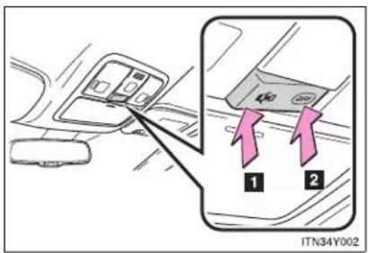
text_image
ITN34Y0021 Door position
The personal/interior lights come on when a door is opened. They turn off when the doors are closed.
2 "OFF"
The personal/interior lights can be individually turned on or off.
Personal/interior lights
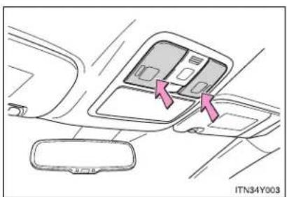
natural_image
Interior view of a car dashboard with two compartments and directional arrows indicating movement (no text or symbols)On/off
The illuminated entry system is activated even if the light is turned off when the personal/interior light main switch is in door position.
Personal lights

text_image
ITN34Y004On/off
Personal lights also turn on when either of the doors is opened. Closing the doors will turn the lights off.
■ Illuminated entry system
▶ Vehicles with smart entry & start system
The lights automatically turn on/off according to "ENGINE START STOP" switch mode, the presence of the electronic key, whether the doors are locked/unlocked, and whether the doors are open/closed.
▶ Vehicles without smart entry & start system
The lights automatically turn on/off according to the engine switch position, whether the doors are locked/unlocked, and whether the doors are open/closed.
■ To prevent the battery from being discharged
If the lights remain on when the door is not fully closed and the personal/interior light main switch is in the door position, the lights will go off automatically after 20 minutes.
■ Customization that can be configured at any authorized Toyota dealer or repairer, or another duly qualified and equipped professional
Settings (e.g. The time elapsed before lights turn off) can be changed. (Customizable features → P. 751)
3-4. Using the storage features List of storage features

text_image
1 2 3 4 4 8 7 6 5 IT36Y0741 Coin box
5 Cup holders*
2 Overhead console*
6 Console box
3 Glove box
7 Bottle holder
4 Bottle holders
8 Cup holder
*: If equipped
CAUTION
Items that should not be left in the storage spaces
Do not leave glasses, lighters or spray cans in the storage spaces, as this may cause the following when cabin temperature becomes high:
- Glasses may be deformed by heat or cracked if they come into contact with other stored items.
● Lighters or spray cans may explode. If they come into contact with other stored items, the lighter may catch fire or the spray can may release gas, causing a fire hazard.
Glove box
▶ Left-hand drive vehicles
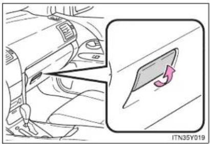
text_image
ITN35Y019Pull up the lever to open the glove box.
▶ Right-hand drive vehicles
The glove box can be opened by pulling the lever, locked and unlocked by using the key.

text_image
1 2 3 ITN35Y0201 Open
2 Lock
3 Unlock
Glove box light
The glove box light turns on when the tail lights are on.

CAUTION
While driving
Keep the glove box closed.
Injuries may result in the event of sudden braking, sudden swerving or an accident.
Console box

text_image
1 2 3 ITN35Y0031 Pull up the lever to release the lock.
2 Slide the armrest.
3 Pull up the lever and lift the armrest to open.
CAUTION
While driving
Keep the console box closed.
Injuries may result in the event of sudden braking, sudden swerving or an accident.
Overhead console (if equipped)
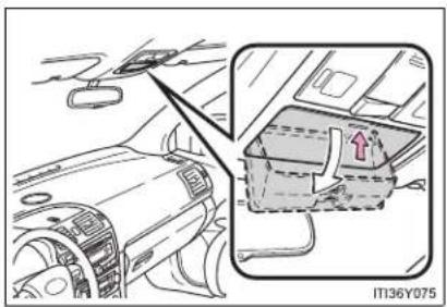
natural_image
Interior view of a car dashboard and infotainment panel (no text or symbols visible)Push the lid.
The overhead console is useful for temporarily storing small items.

CAUTION

While driving
Do not leave the overhead console open. Items may fall out and cause injury.
Cup holders
▶ Front

natural_image
Interior view of a car dashboard and air vent system (no text or symbols visible)Vehicles with the cup holder lid: open the cup holder lid.
▶ Rear (if equipped)

text_image
ITN35Y006Pull down the armrest and open the lid.
CAUTION
Items unsuitable for the cup holder
Do not place anything other than cups or aluminum cans in the cup holders. Other items may be thrown out of the holders in the event of an accident or sudden braking and cause injury. If possible, cover hot drinks to prevent burns.
When not in use
Keep the cup holders closed. Injuries may result in the event of sudden braking, sudden swerving or an accident.
Bottle holders
▶ Front type A

natural_image
Interior view of a car showing the dashboard and steering wheel (no text or symbols visible)▶ Front type B

natural_image
Car interior view showing a car seatbelt switch and a highlighted compartment, with no visible text or symbols.Slide the armrest.
▶ Rear

natural_image
Diagram of a car interior showing a hand holding a steering wheel and a magnified view of the dashboard (no text or symbols present)■ The front bottle holder (type B) can be moved
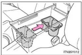
natural_image
Diagram of a mechanical or electrical component with internal components and a pink arrow indicating direction (no text or symbols)The position can be altered by sliding back and forth.
NOTICE
■ Items that should not be stowed in the bottle holders
Put the cap on before stowing a bottle. Do not place open bottles in the bottle holders, or glasses and paper cups containing liquid. The contents may spill and glasses may break.
Coin box
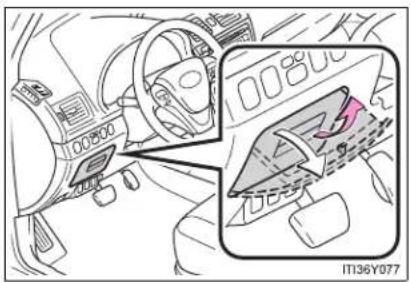
natural_image
Interior view of a car dashboard and steering wheel (no visible text or symbols)Pull up the lever.

CAUTION

While driving
Keep the coin box closed.
Injuries may result in the event of sudden braking, sudden swerving or an accident.
3-5. Other interior features
Sun visors

text_image
2 1 ITN36Y0011 Forward position: Flip down.
2 Side position:
Flip down, unhook, and
swing to the side.
3-5. Other interior features
Vanity mirror
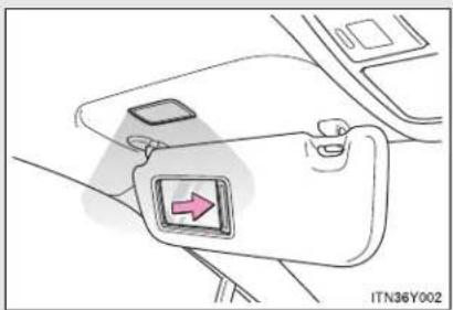
natural_image
Diagram of a car seatbelt with a directional arrow indicator (no text or symbols)Slide the cover.
The light turns on when the cover is opened.
3-5. Other interior features
Ashtray

text_image
IT137Y001Press in and release the lid to open.
Pull the ashtray to remove.

CAUTION
When not in use
Keep the ashtray closed.
Injuries may result in the event of sudden braking, sudden swerving or an accident.
To prevent fire
- Fully extinguish matches and cigarettes before putting them in the ashtray, then make sure the ashtray is fully closed.
Do not place paper or any other type of flammable object in the ashtray.
3-5. Other interior features
Cigarette lighter

text_image
IT137Y002Press in and release the lid to open, and push the cigarette lighter down.
The cigarette lighter will pop up when ready for use.
■ The cigarette lighter can be used when
▶ Vehicles with smart entry & start system
The "ENGINE START STOP" switch is in ACCESSORY or IGNITION ON mode.
▶ Vehicles without smart entry & start system
The engine switch is in the "ACC" or "ON" position.

CAUTION
When not in use
Keep the lid closed.
Injuries may result in the event of sudden braking, sudden swerving or an accident.
■ To avoid burns or fires
- Do not touch the metal parts of the cigarette lighter.
Do not hold the cigarette lighter down. It could overheat and cause a fire. - Do not insert anything other than the cigarette lighter into the outlet.
3-5. Other interior features
Power outlet
The power outlet can be used for 12 V accessories that run on less than 10 A.
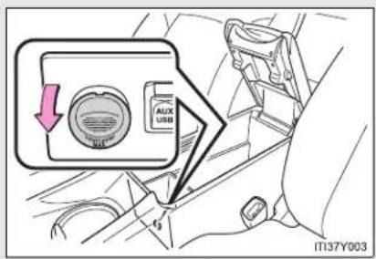
text_image
AUX USD IT137Y003The power outlet can be used when
▶ Vehicles with smart entry & start system
The "ENGINE START STOP" switch is in ACCESSORY or IGNITION ON mode.
▶ Vehicles without smart entry & start system
The engine switch is in the "ACC" or "ON" position.
NOTICE
■ To avoid damaging the power outlet
Close the power outlet lid when not in use.
Foreign objects or liquids that enter the power outlet may cause a short circuit.
■ To prevent the fuse from being blown
Do not use an accessory that uses more than 12 V/10 A.
To prevent the battery from being discharged
Do not use the power outlet longer than necessary when the engine is not running.
3-5. Other interior features
Seat heaters\*

text_image
1 2 3 4 5 6 7 8 9 IT137Y0041 Left-hand drive vehicles: For driver's seat Right-hand drive vehicles: For front passenger's seat
2 Left-hand drive vehicles: For front passenger's seat Right-hand drive vehicles: For driver's seat
3 On The indicator light comes on.
4 Adjusts the seat temperature The further you turn the dial upward, the warmer the seat becomes.
■ The seat heaters can be used when
▶ Vehicles with smart entry & start system
The "ENGINE START STOP" switch is in IGNITION ON mode.
▶ Vehicles without smart entry & start system
The engine switch is in the "ON" position.
*: If equipped

CAUTION
Burns
- Use caution when seating the following persons in a seat with the seat heater on to avoid the possibility of burns:
- Babies, small children, the elderly, the sick and the disabled
- Persons with sensitive skin
- Persons who are fatigued
- Persons who have taken alcohol or drugs that induce sleep (sleeping drugs, cold remedies, etc.)
- Do not cover the seat with anything when using the seat heater.
Using the seat heater with a blanket or cushion increases the temperature of the seat and may lead to overheating.

NOTICE
■ To prevent seat heater damage
Do not put unevenly weighted objects on the seat and do not stick sharp objects (needles, nails, etc.) into the seat.
■ To prevent battery discharge
Turn the switches off when the engine is not running.
3-5. Other interior features
Armrest
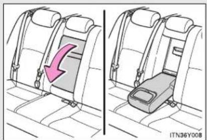
natural_image
Side-by-side illustration of a car seatbelt with a highlighted seatbelt and arrow indicating compression (no text or symbols)Pull the armrest down for use.

NOTICE
To prevent damage to the armrest Do not place too much strain on the armrest.
3-5. Other interior features
Trunk/luggage compartment storage extension\*
Long objects can be loaded in the vehicle by utilizing the trunk/luggage compartment space and rear seat area.

text_image
STEP 1 ITN36Y009Pull down the armrest.
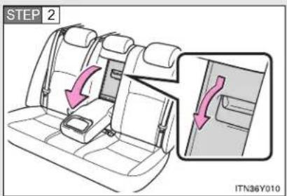
text_image
STEP 2 ITN36Y010Open the trunk/luggage compartment door cover.

CAUTION

When not in use
Ensure that the trunk/luggage compartment door is closed. In the event of sudden braking, items stored in the trunk/luggage compartment may be thrown forward into the cabin, resulting in injury.
*: If equipped
3-5. Other interior features
Panoramic roof shade (wagon)\*
Use the overhead switches to open or close the panoramic roof shade.

text_image
2 1 OFF ITN36Y0111 Close
To stop partway, press the switch lightly.
2 Open
To stop partway, press the switch lightly.
The panoramic roof shade can be operated when
▶ Vehicles with smart entry & start system
The "ENGINE START STOP" switch is in IGNITION ON mode.
▶ Vehicles without smart entry & start system
The engine switch is in the "ON" position.
Jam protection function
If an object is detected between the panoramic roof shade and the frame while closing, travel is stopped and the panoramic roof shade opens slightly.
■ If the panoramic roof shade cannot be closed automatically
If the switch is kept depressed, the panoramic roof shade can be closed manually. If the automatic function will not operate while the panoramic roof shade is closed, push and hold the switch and open the panoramic roof shade fully. It will then be possible to use automatic operation once again.
*: If equipped

CAUTION
■ When closing the panoramic roof shade
Observe the following precautions.
Failing to do so may result in death or serious injury.
- Check to make sure that all passengers do not have any part of their bodies in a position where they could be caught when the panoramic roof shade is being operated.
- Do not allow children to operate the panoramic roof shade. Closing the panoramic roof shade on someone can cause death or serious injury.
Jam protection function
- Never try jamming any part of your body to activate the jam protection function intentionally.
- The jam protection function may not work if something gets caught just before the panoramic roof shade fully closes.

CAUTION
■ To prevent burns or injury
Observe the following precautions.
Although the jam protection function has been installed, make sure that passenger's hands and faces are not caught in the panoramic roof shade while it is closing. Also, as there is a chance that the jam protection function will not react just before closing, make sure not to catch fingers etc. in the roof.
- The opening or closing of the panoramic roof shade can be stopped by pressing the switch.
- If the panoramic roof shade will not close (for example, due to a malfunction in the jam protection function), the shade can be closed by pressing and holding the switch.
- The jam protection function may operate if a load or impact, similar to that applied when a foreign object is caught in the roof shade, is applied by environmental or driving conditions.
The underside of the roof will become hot if the vehicle is left in the direct sunlight for a long period of time. Do not touch the parts inside the gap between the roof underside and the roof shade, as you may burn yourself.
- Do not touch any rough or sheared parts of the roof underside, as you may injure yourself.
3-5. Other interior features
Rear sunshade (sedan)\*

text_image
1 2 ITN36Y0121 Pull the tab up.
2 Hook the sunshade on to the anchors.
To lower the sunshade, pull the tab slightly to unhook the shade, and lower it slowly.
NOTICE
To ensure normal operation of the sunshade
Observe the following precautions.
- Do not place anything where it may hinder the opening/closing of the sun-shade.
Do not place anything on the sunshade.
*: If equipped
3-5. Other interior features
Rear side sunshades (sedan)\*

text_image
Diagram illustrating car seatbelting and lifting mechanism, showing two steps with arrows and labels1 Pull the tab up.
2 Hook the sunshade on to the anchors.
To lower the sunshade, pull the tab slightly to unhook the shade, and lower it slowly.
NOTICE
To ensure normal operation of the sunshade
Observe the following precautions.
- Do not place anything where it may hinder the opening/closing of the sun-shade.
Do not place anything on the sunshade.
*: If equipped
3-5. Other interior features
Floor mats
Use only floor mats designed specifically for vehicles of the same model and model year as your vehicle. Fix them securely in place onto the carpet.
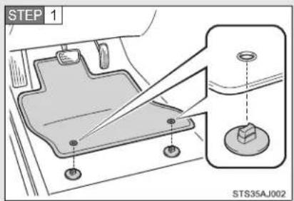
text_image
STEP 1 STS35AJ002Insert the retaining hooks (clips) into the floor mat eye-lets.

text_image
STEP 2 STS35AN002Turn the upper knob of each retaining hook (clip) to secure the floor mats in place.
*: Always align the △marks.
The shape of the retaining hooks (clips) may differ from that shown in the illustration.

CAUTION
Observe the following precautions.
Failure to do so may cause the driver's floor mat to slip, possibly interfering with the pedals while driving. An unexpectedly high speed may result or it may become difficult to stop the vehicle, leading to a serious accident.
When installing the driver's floor mat
- Do not use floor mats designed for other models or different model year vehicles, even if they are Toyota Genuine floor mats.
- Only use floor mats designed for the driver's seat.
● Always install the floor mat securely using the retaining hooks (clips) provided.
Do not use two or more floor mats on top of each other. - Do not place the floor mat bottom-side up or upside-down.
Before driving
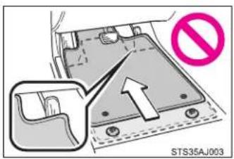
text_image
STS35AJ003- Check that the floor mat is securely fixed in the correct place with all the provided retaining hooks (clips). Be especially careful to perform this check after cleaning the floor.
With the engine stopped and the shif lever in "P" (Multidrive or automatic transmission) or "N" (manual transmission), fully depress each pedal to the floor to make sure it does not interfere with the floor mat.
3-5. Other interior features
Trunk features (sedan)
Cargo hooks
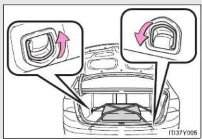
text_image
11137Y005Cargo hooks are provided for securing loose items.
■ First-aid kit storage belt
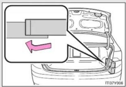
text_image
IT137Y006Luggage mat

text_image
STEP 1 IT137Y007Pull the lever upwards when lifting the luggage mat up.

text_image
STEP 2 ITI37Y008The lever can be hooked on the edge of the trunk.
CAUTION
■ When the cargo hooks are not in use
To avoid injury, always return the cargo hooks to their positions when they are not in use.
NOTICE
When closing the trunk
Do not leave the luggage mat lever hooked on the edge of the trunk. The luggage mat may get damaged.
3-5. Other interior features
Luggage compartment features (wagon)
Cargo hooks
▶ Vehicles with deck rail

text_image
IT137Y009Cargo hooks are provided for securing loose items.
▶ Vehicles without deck rail
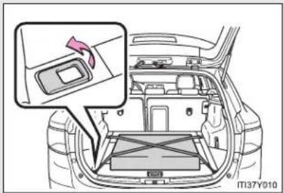
natural_image
Interior view of a car showing the dashboard and seat area with a highlighted component (no text or symbols visible)3-5. Other interior features
Auxiliary box
▶ Front
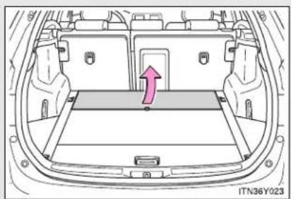
natural_image
Top-down line drawing of a car backseat with a highlighted vent and arrow (no text or symbols)Lift the front deck board.
▶ Rear

text_image
STEP 1 IT37Y011Pull the lever upwards when lifting the rear deck board.
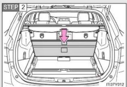
text_image
STEP 2 IT37Y012Press down the rear deck board.
▶ Side
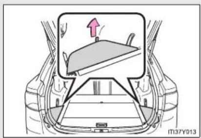
natural_image
Diagram of a car interior showing a steering wheel and dashboard, with an arrow indicating direction (no text or symbols present)Lift the side deck board.
Separating luggage compartment (if equipped)
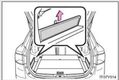
text_image
IT37Y014The deck side board can be used to separate the luggage compartment.
Remove the deck side board and insert it upright into the groove.
Luggage cover (if equipped)

text_image
ITN36Y028Pull out the luggage cover and hook it on the anchors.
3-5. Other interior features
Separation net
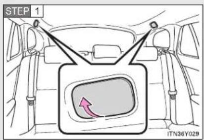
text_image
STEP 1 ITN36Y029Open the cover.

text_image
STEP 2 ITN36Y030Take the strap, lift the separation net and insert it into the hole.
Removing luggage cover
The luggage cover can be removed by following the procedure below.
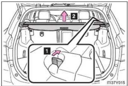
text_image
2 1 IT37Y0151 Pull the release lever
2 Lift up
Removing the separation net
The separation net can be removed by following the procedure below.
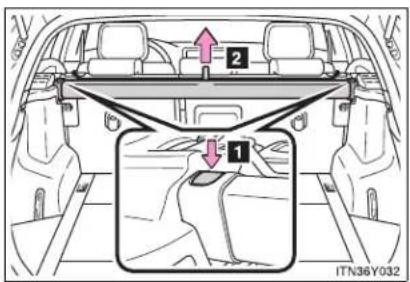
text_image
Diagram showing car interior with labeled parts and directional arrows, including section 1 and section 2 with arrows and a magnified inset.1 Push the release button
2 Lift up
3-5. Other interior features
■ The cargo hooks can be moved (vehicles with deck rail)

text_image
IT137Y016Pushing and holding the center switch allows the cargo hooks to be moved forwards and backwards.
■ Stowing the luggage cover (vehicles without deck rail)

text_image
STEP 1 U4 U2 U1 IT137Y017Remove the side deck board and open the rear deck board.
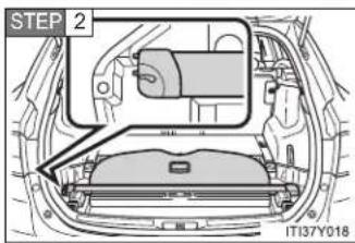
text_image
STEP 2 1T137Y018Move the release lever towards the left side of the auxiliary box, and set into the auxiliary box.
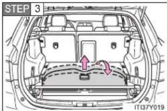
text_image
STEP 3 IT13/Y019Pull the front edge of the luggage cover out a small amount, and fold it forward to store.
■ Stowing the separation net (vehicles without deck rail)

text_image
STEP 1 ITN36Y033Remove the side deck boards and open the rear deck board.

text_image
STEP 2 IT137Y020Move the separation net hook towards the forwards underside and set the separation net into the auxiliary box.

CAUTION
While driving
Do not place anything on the luggage cover. Such items may be thrown about and possibly injure people in the vehicle during sudden braking, sudden swerving or an accident.
■ When the cargo hooks are not in use
To avoid injury, always return the cargo hooks to their positions when they are not in use.
3-5. Other interior features
Maintenance and care
4
4-1. Maintenance and care
Cleaning and protecting
the vehicle exterior ..... 516
Cleaning and protecting
the vehicle interior ..... 521
4-2. Maintenance
Maintenance
requirements.... 524
4-3. Do-it-yourself maintenance
Do-it-yourself service
precautions 527
Hood 531
Positioning a floor jack..... 533
Engine compartment...... 535
Tires.... 552
Tire inflation pressure ..... 556
Wheels.... 558
Air conditioning filter ..... 560
Key battery.... 564
Checking and replacing
fuses 569
Light bulbs 585
4-1. Maintenance and care
Cleaning and protecting the vehicle exterior
Perform the following to protect the vehicle and maintain it in prime condition.
- Working from top to bottom, liberally apply water to the vehicle body, wheel wells and underside of the vehicle to remove any dirt and dust.
Wash the vehicle body using a sponge or soft cloth, such as a chamois. - For hard-to-remove marks, use car wash soap and rinse thoroughly with water.
- Wipe away any water.
● Wax the vehicle when the waterproof coating deteriorates.
If water does not bead on a clean surface, apply wax when the vehicle body is cool.
■ Automatic car washes
- Fold the mirrors and remove the antenna (wagon) before washing the vehicle. Start washing from the front of the vehicle. Make sure to re-install the antenna (wagon) and extend the mirrors before driving.
- Brushes used in automatic car washes may scratch the vehicle surface and harm your vehicle's paint.
- Vehicles with the rain-sensing windshield wipers: Turn the wipers off before washing the vehicle.
■ High pressure car washes
- Do not allow the nozzles of the car wash to come within close proximity of the windows.
- Before car wash, check that the fuel filler door on your vehicle is closed properly.
■ Aluminum wheels (if equipped)
- Remove any dirt immediately by using a neutral detergent. Do not use hard brushes or abrasive cleaners. Do not use strong or harsh chemical cleaners.
Use the same mild detergent and wax as used on the paint.
- Do not use detergent on the wheels when they are hot, for example after driving for long distance in the hot weather.
- Wash detergent from the wheels immediately after use.
■ Bumpers and side moldings
Do not scrub with abrasive cleaners.

CAUTION
■ Caution about the exhaust pipe
Exhaust gasses cause the exhaust pipe to become quite hot.
When washing the vehicle, be careful not to touch the pipe until it has cooled sufficiently, as touching a hot exhaust pipe can cause burns.
■ When cleaning the windshield (vehicles with rain-sensing windshield wipers)
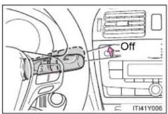
text_image
Off IT41Y006Set the wiper switch to off.
If the wiper switch is in "AUTO", the wipers may operate unexpectedly in the following situations, and may result in hands being caught or other serious injuries and cause damage to the wiper blades.
- When the upper part of the windshield where the raindrop sensor is located is touched by hand
- When a wet rag or similar is held close to the raindrop sensor
- If something bumps against the windshield
- If you directly touch the raindrop sensor body or if something bumps into the raindrop sensor

NOTICE
■ To prevent deterioration and corrosion on the body and components (aluminum wheels etc.)
- Wash the vehicle immediately in the following cases:
• After driving near the sea coast
• After driving on salted roads - If you see coal tar or tree sap on the paint surface
- If you see dead insects or insect droppings on the paint
• After driving in an area contaminated with soot, oily smoke, mine dust, iron powder or chemical substances - If the vehicle becomes heavily soiled in dust or mud
- If liquids such as benzene and gasoline are spilled on the paint surface
- If the paint is chipped or scratched, have it repaired immediately.
- To prevent the wheels from corroding, remove any dirt and store in a place with low humidity when storing the wheels.
■ Cleaning the exterior lights
- Wash carefully. Do not use organic substances or scrub with a hard brush. This may damage the surfaces of the lights.
- Do not apply wax on the surfaces of the lights. Wax may cause damage to the lenses.
■ Antenna installation and removal precautions (wagon only)
Before driving, ensure that the antenna is installed.
- When the antenna is removed, such as before entering an automatic car wash, make sure to store it in a suitable place so as not to lose it. Also, before driving, make sure to reinstall the antenna in its original position.

NOTICE
■ To prevent damage to the windshield wiper arms
When lifting the wiper arms away from the windshield pull the driver side wiper arm upward first, and repeat for the passenger side. When returning the wipers to their original position, do so from the passenger side first.
■ When using an automatic car wash (vehicles with rain-sensing wind-shield wipers)
Turn off the wiper switch. If the wiper switch is in "AUTO", the wipers may operate and the wiper blades may be damaged.
4-1. Maintenance and care
Cleaning and protecting the vehicle interior
The following procedures will help protect your vehicle's interior and keep it in top condition:
■ Protecting the vehicle interior
Remove dirt and dust using a vacuum cleaner. Wipe dirty surfaces with a cloth dampened with lukewarm water.
■ Cleaning the leather areas
- Remove dirt and dust using a vacuum cleaner.
- Wipe any excess dirt and dust with a soft cloth dampened with diluted detergent.
Use a diluted water solution of approximately 5% neutral wool detergent. - Wring out any excess water from the cloth and thoroughly wipe off all remaining traces of detergent.
- Wipe the surface with a dry, soft cloth to remove any remaining moisture. Allow the leather to dry in a shaded ventilated area.
■ Synthetic leather areas
- Remove loose dirt using a vacuum cleaner.
- Apply a mild soap solution to the synthetic leather using a sponge or soft cloth.
- Allow the solution to soak in for a few minutes. Remove the dirt and wipe off the solution with a clean, damp cloth.
Caring for leather areas
Toyota recommends cleaning the interior of the vehicle at least twice a year to maintain the quality of the vehicle's interior.
■ Shampoing the carpets
There are several commercial foaming-type cleaners available. Use a sponge or brush to apply the foam. Rub in overlapping circles. Do not apply water. Excellent results are obtained by keeping the carpet as dry as possible.
Seat belts
Clean with mild soap and lukewarm water using a cloth or sponge. Also check the belts periodically for excessive wear, fraying or cuts.

CAUTION
Water in the vehicle
- Do not splash or spill liquid in the vehicle. Doing so may cause electrical components etc. to malfunction or catch fire.
- Do not get any of the SRS components or wiring in the vehicle interior wet. (→P. 157)
Electrical malfunction may cause the airbags to deploy or not function properly, resulting in death or serious injury.
■ Cleaning the interior (especially instrument panel)
Do not use polish wax or polish cleaner. The instrument panel may reflect off the windshield, obstructing the driver's view and leading to an accident, resulting in death or serious injury.

NOTICE
- Cleaning detergents
- Do not use organic substances such as benzene or gasoline, acidic or alkaline solutions, dye, bleach or other detergent. Doing so may discolor the vehicle interior or cause streaks or damage to painted surfaces.
- Do not use polish wax or polish cleaner. The instrument panel's or other interior part's painted surface may be damaged.
■ Preventing damage to leather surfaces
Observe the following precautions to avoid damage to and deterioration of leather surfaces.
- Remove any dust or dirt on leather surfaces immediately.
- Do not expose the vehicle to direct sunlight for extended periods of time. Park the vehicle in the shade, especially during summer.
- Do not place items made of vinyl, plastic, or that contain wax on the upholstery, as they may stick to the leather surface if the vehicle interior heats up significantly.
Water on the floor
Do not wash the vehicle floor with water.
Vehicle systems such as the audio system may be damaged if water comes into contact with electrical components under the floor of the vehicle, and may also cause the body to rust.
- Cleaning the inside of the rear window or right-side rear quarter window
- Do not use glass cleaner to clean the rear window or right-side rear quarter window (wagon), as this may cause damage to the rear window defogger heater wires or antenna. Use a cloth dampened with lukewarm water to gently wipe the window clean. Wipe the window in strokes running parallel to the heater wires or antenna.
- Be careful not to scratch or damage the heater wires or antenna.
4-2. Maintenance
Maintenance requirements
To ensure safe and economical driving, day-to-day care and regular maintenance is essential. Toyota recommends the following maintenance.
■ Scheduled maintenance
Scheduled maintenance be performed at specified intervals according to the maintenance schedule.
For full details of your maintenance schedule, read the "Toyota Service Booklet" or "Toyota Warranty Booklet".
Do-it-yourself maintenance
What about do-it-yourself maintenance?
Many maintenance items are easy to do yourself if you have a little mechanical ability and a few basic automotive tools.
Note, however, that some maintenance tasks require special tools and skills. These are best performed by qualified technicians. Even if you're an experienced do-it-yourself mechanic, we recommend that repairs and maintenance be conducted by any authorized Toyota dealer or repairer, or another duly qualified and equipped professional. Any authorized Toyota dealer or repairer will keep a record of maintenance, which could be useful should you ever require Warranty Service. Should you choose to select a qualified and equipped professional other than an authorized Toyota repairer to service or maintain your vehicle, we recommend that you request that a record of maintenance be kept.
■ Where to go for service?
In order to maintain your vehicle in the highest possible condition, Toyota recommends that all repairs and service operations be carried out by authorized Toyota dealers or repairers or other duly qualified and equipped professionals. For repairs and services covered by your warranty, please visit an authorized Toyota dealer or repairer, who will use genuine Toyota parts in repairing any difficulties you may encounter. There can also be advantages in utilizing authorized Toyota dealers or repairers for non-warranty repairs and services, as members of the Toyota network will be able to expertly assist you with any difficulties you may encounter.
Your Toyota dealer or repairer, or another duly qualified and equipped professional service department will perform all of the scheduled maintenance on your vehicle-reliably and economically due to their experience with Toyota vehicles.
■ Does your vehicle need repair?
Be on the alert for changes in performance and sounds, and visual tip-offs that indicate service is needed. Some important clues are:
• Engine missing, stumbling, or pinging
• Appreciable loss of power
- Strange engine noises
- A fluid leak under the vehicle (However, water dripping from the air conditioning after use is normal.)
- Change in exhaust sound (This may indicate a dangerous carbon monoxide leak. Drive with the windows open and have the exhaust system checked immediately.)
- Flat-looking tires, excessive tire squeal when cornering, uneven tire wear
4-2. Maintenance
● Vehicle pulls to one side when driving straight on a level road
- Strange noises related to suspension movement
- Loss of brake effectiveness, spongy feeling brake pedal, pedal almost touches the floor, vehicle pulls to one side when braking
● Engine coolant temperature continually higher than normal
If you notice any of these clues, take your vehicle to any authorized Toyota dealer or repairer, or another duly qualified and equipped professional, as soon as possible. Your vehicle may need adjustment or repair.

CAUTION
If your vehicle is not properly maintained
It could result in serious damage to the vehicle and possible personal injury or death.
■ Warning in handling of the battery
Battery posts, terminals and related accessories contain lead and lead compounds which are known to cause brain damage. Wash your hands after handling. (→P. 545)
■ Used engine oil
Used engine oil contains chemicals that have been shown to cause cancer in laboratory animals. Avoid prolonged and repeated contact. Always protect your skin by washing thoroughly with soap and water.
4-3. Do-it-yourself maintenance
Do-it-yourself service precautions
If you perform maintenance yourself, be sure to follow the correct procedures as given in these sections.
| Items Parts and tools | |
| Battery condition (→P. 545) | GreaseConventional wrench(for terminal clamp bolts) |
| Engine coolant level (→P. 543) | Toyota Super Long Life Coolant or similar high quality ethylene glycol based non-silicate, non-amine, non-nitrite and non-borate coolant with long-life hybrid organic acid technology. Toyota Super Long Life Coolant is pre-mixed with 50% coolant and 50% deionized water.Funnel (used only for adding coolant) |
| Engine oil level (→P. 538) | Toyota Genuine Motor Oil or equivalentRag or paper towel, funnel (used only for adding oil) |
4-3. Do-it-yourself maintenance
| Items Parts and tools | |
| Fuses (→P. 569) | ·Fuse with same amperage rating as original |
| Radiator, condenser and inter-cooler (→P. 545) | — |
| Tire inflation pressure (→P. 556) | ·Tire pressure gauge·Compressed air source |
| Washer fluid (→P. 549) | ·Water or washer fluid containing antifreeze (for winter use)·Funnel |

CAUTION
The engine compartment contains many mechanisms and fluids that may move suddenly, become hot, or become electrically energized. To avoid death or serious injury observe the following precautions.
■ When working on the engine compartment
- Keep hands, clothing, and tools away from the moving fan and engine drive belt.
- Be careful not to touch the engine, radiator, exhaust manifold, etc. right after driving as they may be hot. Oil and other fluids may also be hot.
- Do not leave anything that may burn easily, such as paper or rags, in the engine compartment.
- Do not smoke, cause sparks or expose an open flame to fuel or the battery. Fuel and battery fumes are flammable.
- Be extremely cautious when working on the battery. It contains poisonous and corrosive sulfuric acid.
Take care because brake fluid can harm your hands or eyes and damage painted surfaces.
If fluid gets on your hands or in your eyes, flush the affected area with clean water immediately.
If you still experience discomfort, see a doctor.

CAUTION
■ When working near the electric cooling fan or radiator grille
▶ Vehicles with smart entry & start system
Be sure the "ENGINE START STOP" switch is OFF.
With the “ENGINE START STOP” switch in IGNITION ON mode, the electric cooling fan may automatically start to run if the air conditioning is on and/or the coolant temperature is high. (→P. 545)
▶ Vehicles without smart entry & start system
Be sure the engine switch is in the "LOCK" position.
With the engine switch in the "ON" position, the electric cooling fan may automatically start to run if the air conditioning is on and/or the coolant temperature is high. (→P. 545)
Safety glasses
Wear safety glasses to prevent flying or falling material, fluid spray, etc. from getting in the eyes.

NOTICE
If you remove the air cleaner filter
Driving with the air cleaner filter removed may cause excessive engine wear due to dirt in the air. Also a backfire could cause a fire in the engine compartment.
If the brake fluid level is low or high
It is normal for the brake fluid level to go down slightly as the brake pads wear or when the fluid level in the accumulator is high.
If the reservoir needs frequent refilling, it may indicate a serious problem.
4-3. Do-it-yourself maintenance
Hood
Release the lock from the inside of the vehicle to open the hood.
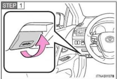
text_image
STEP 1 ITN43Y078Pull the hood release lever.
The hood will pop up slightly.
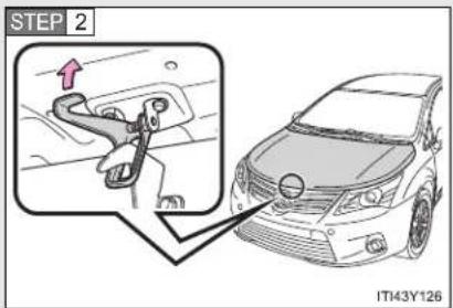
text_image
STEP 2 IT43Y126Lift the hood catch and lift the hood.
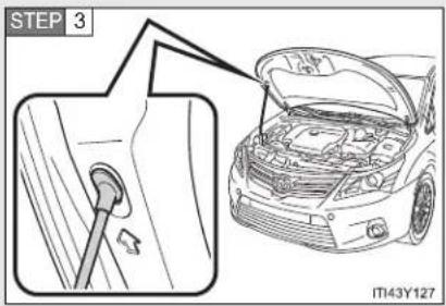
text_image
STEP 3 IT43Y127Hold the hood open by inserting the supporting rod into the slot.

CAUTION
■ Pre-driving check
Check that the hood is fully closed and locked.
If the hood is not locked properly, it may open while the vehicle is in motion and cause an accident, which may result in death or serious injury.
■ After installing the support rod into the slot
Make sure the rod supports the hood securely from falling down on to your head or body.

NOTICE
■ When closing the hood
Be sure to return the support rod to its clip before closing the hood. Closing the hood with the support rod up could cause the hood to bend.
4-3. Do-it-yourself maintenance
Positioning a floor jack
When raising your vehicle with a floor jack, position the jack correctly. Improper placement may damage your vehicle or cause injury.
▶ Front
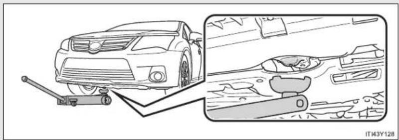
natural_image
Diagram showing a car with a lever and a close-up of its dashboard and steering wheel (no text or symbols present)▶ Rear
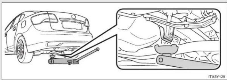
natural_image
Diagram showing a car being lifted by a lift, with a close-up view of the engine and suspension components (no text or symbols)
CAUTION
■ When raising your vehicle
Make sure to observe the following to reduce the possibility of death or serious injury.

natural_image
Line drawing of a mechanical lifting device with labeled parts (no text or symbols on the diagram itself)- Lift up the vehicle using a floor jack such as the one shown in the illustration.
- When using a floor jack, follow the instructions of the manual provided with the jack.
- Do not use the jack that was supplied with your vehicle.
- Do not put any part of your body or get underneath the vehicle supported only by the floor jack.
● Always use floor jack and/or automotive jack stands on a solid, flat, level surface.
Do not start the engine while the vehicle is supported by the floor jack. - Stop the vehicle on level firm ground, firmly set the parking brake and put the shift lever in "P" (Multidrive or automatic transmission) or "R" (manual transmission).
Make sure to set the floor jack properly at the jack point. Raising the vehicle with an improperly positioned floor jack will damage the vehicle and may cause the vehicle to fall off the floor jack. - Do not raise the vehicle while someone is in the vehicle.
- When raising the vehicle, do not place any objects on top of or underneath the floor jack.
4-3. Do-it-yourself maintenance
Engine compartment
▶ Gasoline engine

text_image
1 2 3 4 5 6 7 8 9 ITI43Y1301 Washer fluid tank ( P. 549)
2 Engine coolant reservoir
(→P. 543)
3 Engine oil filler cap
(→P. 539)
4 Engine oil level dipstick
(→P. 538)
5 Battery (→P. 545)
6 Fuse box (→P. 569)
7 Cooling fan
8 Condenser (→P. 545)
9 Radiator (→P. 545)
▶ Diesel engine

text_image
1 2 3 4 5 6 7 8 9 10 11 ITI43Y131a1 Washer fluid tank ( P. 549)
2 Engine coolant reservoir ( P. 543)
3 Engine oil level dipstick
(→P. 538)
4 Engine oil filler cap
(→P. 539)
5 Fuel filter ( P. 550, 713)
6 Fuse box (→P. 569)
7 Battery ( P. 545)
8 Cooling fans
9 Condenser ( P. 545)
10 Intercooler ( P. 545)
11 Radiator ( P. 545)
Engine compartment cover
■ Removing the engine compartment cover
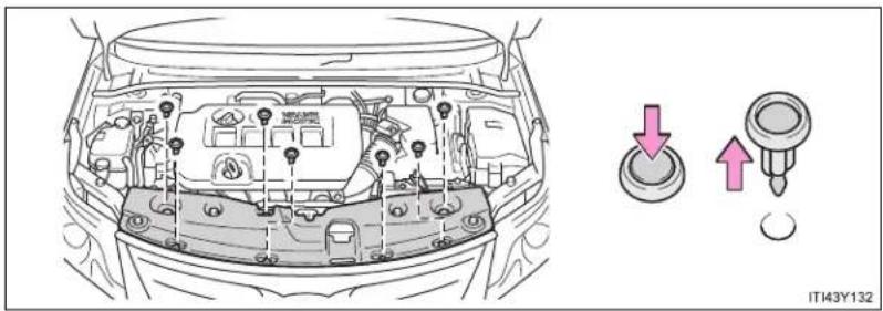
natural_image
Line drawing of a car engine bay with three directional buttons (down, up, down arrow) pointing to the dashboard area, no text or symbols present.Installing the clips

text_image
1 2 3 4 ITN43Y0101 Rotate center portion
2 Push up center portion
3 Insert
4 Press
NOTICE
■ After installing an engine compartment cover
Make sure that the cover is securely installed in its original position.
Engine oil
With the engine at operating temperature and turned off, check the oil level on the dipstick.
Checking the engine oil
STEP 1 Park the vehicle on level ground. After warming up the engine and turning it off, wait more than 5 minutes for the oil to drain back into the bottom of the engine.
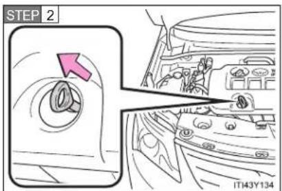
text_image
STEP 2 IT143Y134Hold a rag under the end and pull the dipstick out.
STEP 3 Wipe the dipstick clean.
STEP 4 Reinsert the dipstick fully.
STEP 5 Holding a rag under the end, pull the dipstick out and check the oil level.
STEP 6 Wipe the dipstick and reinsert it fully.
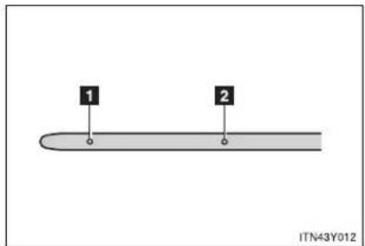
text_image
1 2 ITN43Y0121 Low
2 Full
■ Adding engine oil

text_image
MAGIT IT143Y135If the oil level is below or near the low level mark, add engine oil of the same type as already in the engine.
Make sure to check the oil type and prepare the items needed before adding oil.
| Engine oil selection →P. 727 |
| Items Clean funnel |
STEP 1 Remove the oil filler cap.
STEP 2 Add engine oil slowly, checking the dipstick.
STEP 3 Install the filler cap, turning it clockwise.
The approximate quantity of oil needed to raise the level between low and full on the dipstick is indicated as follows:
▶ Gasoline engine
1.5 L (1.6 qt., 1.3 Imp.qt.)
▶ 1AD-FTV engine
Vehicles with DPF catalytic converter:
1.6 L (1.7 qt., 1.4 Imp.qt.)
Vehicles without DPF catalytic converter:
1.7 L (1.8 qt., 1.5 Imp.qt.)
▶ 2AD-FTV and 2AD-FHV engines
1.6 L (1.7 qt., 1.4 Imp.qt.)
■ Engine oil consumption
- The amount of engine oil consumed depends on the oil viscosity, the quality of the oil and the way the vehicle is driven.
- More oil is consumed under driving conditions such as high speeds and frequent acceleration and deceleration.
A new engine consumes more oil. - When judging the amount of oil consumption, keep in mind that the oil may have become diluted, making it difficult to judge the true level accurately.
- Oil consumption: Max. 1.0 L per 1000 km (1.1 qt./600 miles, 0.9 Imp.qt./600 miles)
- If you consume more than 1.0 L (1.1 qt., 0.9 Imp.qt.) every 1000 km (600 miles), contact any authorized Toyota dealer or repairer, or another duly qualified and equipped professional.
■ After changing the engine oil (diesel engine)
The oil change system should be reset. Perform the following procedures:
▶ Vehicles with smart entry & start system
STEP 1 Switch the display to trip meter A ( P. 242) when the engine is running.
STEP 2 Turn the "ENGINE START STOP" switch OFF.
STEP 3 While pressing the trip meter reset button, set the "ENGINE START STOP" switch to IGNITION ON mode (but do not start the engine because otherwise the reset mode will be canceled). Continue to press and hold the button until the multi-information display indicates that the reset is complete.
▶ Vehicles without smart entry & start system
STEP 1 Switch the display to trip meter A ( P. 242) when the engine is running.
STEP 2 Turn the engine switch to the "LOCK" position.
STEP 3 While pressing the trip meter reset button, set the engine switch to the "ON" position (but do not start the engine because otherwise the reset mode will be canceled). Continue to press and hold the button until the multi-information display indicates that the reset is complete.

CAUTION
■ Used engine oil
- Used engine oil contains potentially harmful contaminants which may cause skin disorders such as inflammation or skin cancer, so care should be taken to avoid prolonged and repeated contact. To remove used engine oil from your skin, wash thoroughly with soap and water.
- Dispose of used oil and filters only in a safe and acceptable manner. Do not dispose of used oil and filters in household trash, in sewers or onto the ground. Call any authorized Toyota dealer or repairer, or another duly qualified and equipped professional, service station or auto parts store for information concerning recycling or disposal.
- Do not leave used engine oil within the reach of children.

NOTICE
■ To prevent serious engine damage
Check the oil level on regular basis.
■ When replacing the engine oil
- Be careful not to spill engine oil on the vehicle components.
- Avoid overfilling, as the engine could be damaged.
- Check the oil level on the dipstick every time you refill the vehicle.
- Be sure the engine oil filler cap is properly tightened.
Engine coolant
The coolant level is satisfactory if it is between the "FULL" and "LOW" lines on the reservoir when the engine is cold.
▶ Gasoline engine
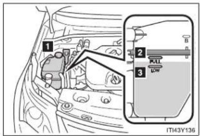
text_image
1 2 3 FULL LOW IT43Y1361 Reservoir cap
2 "FULL"
3 "LOW"
If the level is on or below the "LOW" line, add coolant up to the "FULL" line.
▶ Diesel engine

text_image
1 2 NLO LOW 3 ITI43Y1371 Reservoir cap
2 "FULL"
3 "LOW"
If the level is on or below the "LOW" line, add coolant up to the "FULL" line.
If the coolant level drops within a short time after replenishing
Visually check the radiator, hoses, reservoir cap, radiator cap, drain cock and water pump.
If you cannot find a leak, have any authorized Toyota dealer or repairer, or another duly qualified and equipped professional, test the cap and check for leaks in the cooling system.
Coolant selection
Only use “Toyota Super Long Life Coolant” or similar high quality ethylene glycol based non-silicate, non-amine, non-nitrite, and non-borate coolant with long-life hybrid organic acid technology.
"Toyota Super Long Life Coolant" is a mixture of 50% coolant and 50% deionized water. (Enabled: -35°C [-31°F])
For more details about engine coolant, contact any authorized Toyota dealer or repairer, or another duly qualified and equipped professional.

CAUTION
■ When the engine is hot
Do not remove the coolant reservoir cap.
The cooling system may be under pressure and may spray hot coolant if the cap is removed, causing serious injuries, such as burns.

NOTICE
■ When adding engine coolant
Coolant is neither plain water nor straight antifreeze. The correct mixture of water and antifreeze must be used to provide proper lubrication, corrosion protection and cooling. Be sure to read the antifreeze or coolant label.
If you spill coolant
Be sure to wash it off with water to prevent damage to parts or paint.
Radiator, condenser and intercooler
Check the radiator, condenser and intercooler (diesel engine) and clear any foreign objects.
If any of the above parts are extremely dirty or you are not sure of their condition, have your vehicle checked by any authorized Toyota dealer or repairer, or another duly qualified and equipped professional.

CAUTION
When the engine is hot
Do not touch the radiator, condenser or intercooler, as they may be hot and cause serious injuries, such as burns.
Battery
Check the battery as follows.
Caution symbol
The meanings of each caution symbol on the top of the battery are as follows:
 | No smoking, no naked flames, no sparks |  | Battery acid |
 | Shield eyes |  | Note operating instructions |
 | Keep away from chil-dren |  | Explosive gas |
4-3. Do-it-yourself maintenance
Battery exterior
Make sure that the battery terminals are not corroded and that there are no loose connections, cracks, or loose clamps.

text_image
1 2 1 IT43Y1741 Terminals
2 Hold-down clamp
Before recharging
When recharging, the battery produces hydrogen gas which is flammable and explosive. Therefore, before recharging:
- If recharging with the battery installed on the vehicle, be sure to disconnect the ground cable.
- Make sure the power switch on the charger is off when connecting and disconnecting the charger cables to the battery.
■ After recharging the battery (vehicles with smart entry & start system)
The engine may not start. Follow the procedure below to initialize the system.
STEP 1 Depress the brake pedal with the shift lever in "N".
STEP 2 Open and close any of the doors.
STEP 3 Restart the engine.
■ When replacing the battery
A proper battery should be used. Contact any authorized Toyota dealer or repairer, or another duly qualified and equipped professional.

CAUTION
■ Chemicals in the battery
A battery contains poisonous and corrosive sulfuric acid and may produce hydrogen gas which is flammable and explosive. To reduce the risk of death or serious injury, take the following precautions while working on or near battery:
- Do not cause sparks by touching the battery terminals with tools.
- Do not smoke or light a match near the battery.
- Avoid contact with eyes, skin and clothes.
- Never inhale or swallow electrolyte.
- Wear protective safety glasses when working near the battery.
- Keep children away from the battery.
■ Where to safely charge the battery
Always charge the battery in an open area. Do not charge the battery in a garage or closed room where there is not sufficient ventilation.

CAUTION
■ How to recharge the battery
Only perform a slow charge (5 A or less). The battery may explode if charged at quicker rate.
Emergency measures regarding electrolyte
• If electrolyte gets in your eyes
Flush your eyes with clean water for at least 15 minutes and get immediate medical attention. If possible, continue to apply water with a sponge or cloth while traveling to the nearest medical facility.
• If electrolyte gets on your skin
Wash the affected area thoroughly. If you feel pain or burning, get medical attention immediately.
• If electrolyte gets on your clothes
It can soak through clothing on to your skin. Immediately take off the clothing and follow the procedure above if necessary.
• If you accidentally swallow electrolyte
Drink a large quantity of water or milk. Get emergency medical attention immediately.

NOTICE
■ When recharging the battery
Never recharge the battery while the engine is running. Also, be sure all accessories are turned off.
■ When adding distilled water
- Avoid overfilling. Water spilled during battery recharging may cause corrosion.
- Do not spill distilled water onto the rubber components.
Washer fluid

text_image
ITN43Y020If the fluid level is extremely low, add washer fluid.
Raise the cap keeping your finger pressed down on the hole in the center and check the fluid level in the tube.

CAUTION
■ When refilling the washer fluid
Do not refill the washer fluid when the engine is hot or running, as the washer fluid contains alcohol and may catch fire if spilled on the engine etc.

NOTICE
- Do not use any fluid other than washer fluid
Do not use soapy water or engine antifreeze instead of washer fluid. Doing so may cause streaking on the vehicle's painted surfaces.
Diluting washer fluid
Dilute washer fluid with water as necessary. Refer to the freezing temperatures listed on the label of the washer fluid bottle.
Fuel filter (diesel engine)
You may drain the fuel filter yourself. However, as the operation is difficult, we recommend having it drained by any authorized Toyota dealer or repairer, or another duly qualified and equipped professional. Event if you decide to drain it yourself, contact any authorized Toyota dealer or repairer, or another duly qualified and equipped professional.
The water in the fuel filter needs to be drained if the "DRAIN WATER FROM FUEL FILTER" warning message is shown on the multi-information display and a buzzer sounds. (→P. 629)
STEP 1 Turn the "ENGINE START STOP" switch to off (vehicles with smart entry & start system) or the engine switch to the "LOCK" position (vehicles without smart entry & start system).
STEP 2 Place a small tray under the drain plug to catch the water and any fuel that comes out.
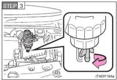
text_image
STEP 3 IT143Y164aTurn the drain plug counterclockwise about 2 to 2 1/2 turns.
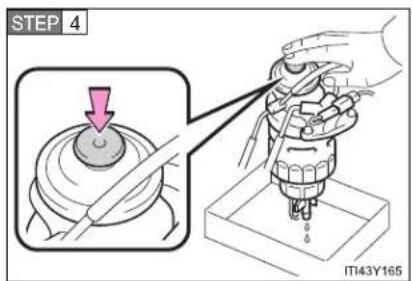
text_image
STEP 4 IT143Y165Operate the priming pump until fuel begins to run out.
STEP 5 After draining, tighten the drain plug by hand.
4-3. Do-it-yourself maintenance
Tires
Replace the tires when the treadwear indicators show.
- Checking tires
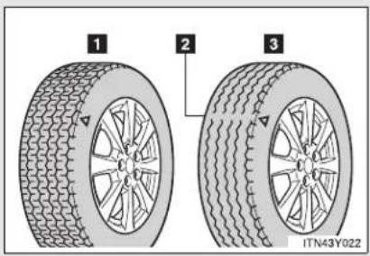
text_image
1 2 3 ITN43Y0221 New tread
2 Treadwear indicator
3 Worn tread
The location of treadwear indicators is shown by the "TWI" or "△" marks, etc., molded on the sidewall of each tire.
Check spare tire condition and inflation pressure if not rotated.
Tire rotation
▶ Vehicles with a spare tire of different wheel type from the installed tires or an emergency puncture repair kit

flowchart
graph TD
    A[" "] <--> B[" "]
    C[" "] <--> D[" "]
    E[" "] <--> F[" "]
    G[" "] <--> H[" "]
    I[" "] <--> J[" "]
    K[" "] <--> L[" "]
    M[" "] <--> N[" "]
    O[" "] <--> P[" "]
    Q[" "] <--> R[" "]
    S[" "] <--> T[" "]
    U[" "] <--> V[" "]
    W[" "] <--> X[" "]
    Y[" "] <--> Z[" "]
    AA["ITN43Y023"]
Rotate the tires in the order shown.
To equalize tire wear and help extend tire life, Toyota recommends that you rotate your tires approximately every 10000 km (6000 miles).
▶ Vehicles with a spare tire of same wheel type as the installed tires
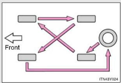
flowchart
graph TD
    A[" "] --> B[" "]
    C[" "] --> D[" "]
    E[" "] --> F[" "]
    G[" "] --> H[" "]
    I[" "] --> J[" "]
    K[" "] --> L[" "]
    M[" "] --> N[" "]
    O[" "] --> P[" "]
    Q[" "] --> R[" "]
    S[" "] --> T[" "]
    U[" "] --> V[" "]
    W[" "] --> X[" "]
    Y[" "] --> Z[" "]
    AA[" "] --> AB[" "]
    AC[" "] --> AD[" "]
    AE[" "] --> AF[" "]
    AG[" "] --> AH[" "]
    AI[" "] --> AJ[" "]
    AK[" "] --> AL[" "]
    AM[" "] --> AN[" "]
    AO[" "] --> AP[" "]
    AQ[" "] --> AR[" "]
    AS[" "] --> AT[" "]
    AU[" "] --> AV[" "]
    AW[" "] --> AX[" "]
    AY[" "] --> AZ[" "]
    BA[" "] --> BB[" "]
    BC[" "] --> BD[" "]
    BE[" "] --> BF[" "]
    BG[" "] --> BH[" "]
    BI[" "] --> BJ[" "]
    BK[" "] --> BL[" "]
    BM[" "] --> BN[" "]
    BO[" "] --> BP[" "]
    BP[" "] --> BQ[" "]
    BR[" "] --> BS[" "]
    BT[" "] --> BU[" "]
    BV[" "] --> BW[" "]
    BX[" "] --> BY[" "]
    BZ[" "] --> CA[" "]
    CB[" "] --> CD[" "]
    CE[" "] --> CF[" "]
    CG[" "] --> DH[" "]
    DI[" "] --> DJ[" "]
    DK[" "] --> DL[" "]
    DJ[" "] --> DW[" "]
    DX[" "] --> DXB[" "]
    DXB --> DXC[" "]
    DXC --> DXD[" "]
    DXD --> DXE[" "]
    DXE --> DXF[" "]
    DXF --> DXG[" "]
    DXG --> DXH[" "]
    DXH --> DXI[" "]
    DXI --> DXJ[" "]
    DXJ --> DXK[" "]
    DXK --> DXL[" "]
    DXL --> DXM[" "]
    DXM --> DXN[" "]
    DXN --> DXO[" "]
    DXO --> DXP[" "]
    DXP --> DXQ[" "]
    DXQ --> DXR[" "]
    DXR --> DXS[" "]
    DXS --> DXT[" "]
    DXT --> DXU[" "]
    DXU --> DXV[" "]
    DXV --> DXW[" "]
    DXW --> DXX[" "]
- When to replace your vehicle's tires
Tires should be replaced if:
- You have tire damage such as cuts, splits, cracks deep enough to expose the fabric or bulges indicating internal damage
- A tire goes flat repeatedly or cannot be properly repaired due to the size or location of a cut or other damage
If you are not sure, consult with any authorized Toyota dealer or repairer, or another duly qualified and equipped professional.
Tire life
Any tire over 6 years old must be checked by a qualified technician even if they have seldom or never been used or damage is not obvious.
If the tread wears down 4 mm (0.16 in.) or more on snow tires
The effectiveness of snow tires is lost.
■ Low profile tires (225/45R18 tires)
Generally, low profile tires will wear more rapidly and tire grip performance will be reduced on snowy and/or icy roads when compared to standard tires. Be sure to use snow tires or tire chains on snowy and/or icy roads and drive carefully at a speed appropriate for road and weather conditions.

CAUTION
■ When inspecting or replacing tires
Observe the following precautions to prevent accidents.
Failure to do so may cause damage to parts of the drive train, as well as dangerous handling characteristics, which may lead to an accident resulting in death or serious injury.
- Do not mix tires of different makes, models or tread patterns.
Also, do not mix tires of remarkably different treadwear. - Do not use tire sizes other than those recommended by Toyota.
- Do not mix differently constructed tires (radial, bias-belted or bias-ply tires).
- Do not mix summer, all season and snow tires.
- Do not use tires that have been used on another vehicle.
Do not use tires if you do not know how they were used previously.

NOTICE
- Driving on rough roads
Take particular care when driving on roads with loose surfaces or pot holes. These conditions may cause losses in tire inflation pressure, reducing the cushioning ability of the tires. In addition driving on rough roads may cause damage to the tires themselves, as well as the vehicle's wheels and body.
■ Low profile tires (225/45R18 tires)
Low profile tires may cause greater damage than usual to the wheel when receiving impact from the road surface. Therefore pay attention to the following:
- Be sure to use proper tire inflation pressure. If tires are under-inflated, they may be damaged more severely.
- Avoid pot holes, uneven pavement, curbs and other road hazards. Failure to do so can lead to severe tire and wheel damage.
Extra Load tires (225/45R18 95W tires)
2AD-FTV and 2AD-FHV engines: Vehicles fitted with 18 inch tires have Extra Load capacity (95W) due to front axle weight. When replacing the tires in after market, the customer should select tires with same load index.
■ If tire inflation pressures become low while driving
Do not continue driving, or your tires and/or wheels may be ruined.
4-3. Do-it-yourself maintenance
Tire inflation pressure
Make sure to maintain the proper tire inflation pressure. Tire inflation pressure should be checked at least once per month. However, Toyota recommends that tire inflation pressure be checked once every two weeks. (→P. 739)
■ Effects of incorrect tire inflation pressure
Driving with incorrect tire inflation pressure may result in the following:
- Reduced fuel efficiency
- Reduced driving comfort and tire life
- Reduced safety
- Damage to the drive train
If a tire needs frequent refilling, have it checked by any authorized Toyota dealer or repairer, or another duly qualified and equipped professional.
■ Instructions for checking tire inflation pressure
When checking tire inflation pressure, observe the following:
- Check only when the tires are cold.
If your vehicle has been parked for at least 3 hours and has not been driven for more than 1.5 km or 1 mile, you will get an accurate cold tire inflation pressure reading.
● Always use a tire pressure gauge.
The appearance of the tire can be misleading. In addition, tire inflation pressures that are even just a few pounds off can degrade ride and handling.
- Do not bleed or reduce tire inflation pressure after driving. It is normal for the tire inflation pressure to be higher after driving.
● Never exceed the vehicle capacity weight.
Passengers and luggage weight should be placed so that the vehicle is balanced.

CAUTION
■ Proper inflation is critical to save tire performance
Keep your tires properly inflated. Otherwise, the following conditions may occur and result in an accident causing death or serious injury.
Excessive wear
Uneven wear
Poor handling
- Possibility of blowouts resulting from overheated tires
● Poor sealing of the tire bead
- Wheel deformation and/or tire separation
A greater possibility of tire damage from road hazards

NOTICE
■ When inspecting and adjusting tire inflation pressure
Be sure to reinstall the tire valve caps.
Without the valve caps, dirt or moisture could get into the valve and cause air leakage, which could result in an accident. If the caps have been lost, replace them as soon as possible.
4-3. Do-it-yourself maintenance
Wheels
If a wheel is bent, cracked or heavily corroded, it should be replaced. Otherwise, the tire may separate from the wheel or cause loss of handling control.
Wheel selection
When replacing wheels, care should be taken to ensure that they are equivalent to those removed in load capacity, diameter, rim width, and inset*.
Replacement wheels are available at any authorized Toyota dealer or repairer, or another duly qualified and equipped professional.
*: Conventionally referred to as "offset".
Toyota does not recommend using:
● Wheels of different sizes or types
• Used wheels
● Bent wheels that have been straightened
■ Aluminum wheel precautions
- Use only Toyota wheel nuts and wrenches designed for use with your aluminum wheels.
- When rotating, repairing or changing your tires, check that the wheel nuts are still tight after driving 1600 km (1000 miles).
- Be careful not to damage the aluminum wheels when using tire chains.
- Use only Toyota genuine balance weights or equivalent and a plastic or rubber hammer when balancing your wheels.

CAUTION
■ When replacing wheels
- Do not use wheels that are a different size from those recommended in the Owner's Manual, as this may result in loss of handling control.
- Never use an inner tube in a leaking wheel which is designed for a tubeless tire. Doing so may result in an accident, causing death or serious injury.
■ When installing the wheel nuts

text_image
Tapered portion STSOT00030- Be sure to install the wheel nuts with the tapered ends facing inward. Installing the nuts with the tapered ends facing outward can cause the wheel to break and eventually cause the wheel to come off while driving, which could lead to an accident resulting in death or serious injury.
- Never use oil or grease on the wheel bolts or wheel nuts. Oil and grease may cause the wheel nuts to be excessively tightened, leading to bolt or disc wheel damage. In addition, the oil or grease can cause the wheel nuts to loosen and the wheel may fall off, causing an accident and resulting in death or serious injury. Remove any oil or grease from the wheel bolts or wheel nuts.
4-3. Do-it-yourself maintenance
Air conditioning filter
The air conditioning filter must be cleaned or changed regularly to maintain air conditioning efficiency.
Removal method
STEP 1 Vehicles with smart entry & start system: Turn the "ENGINE START STOP" switch OFF.
Vehicles without smart entry & start system: Turn the engine switch to the "LOCK" position.
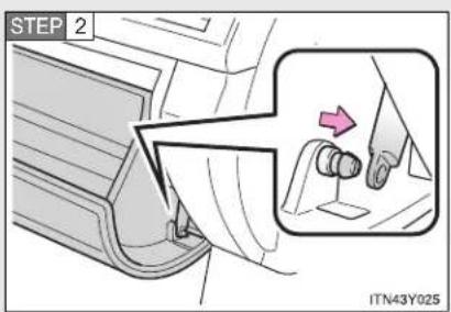
text_image
STEP 2 ITN43Y025Open the glove box. Slide off the damper.
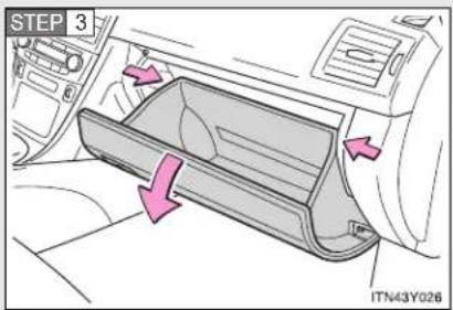
text_image
STEP 3 ITN43Y026Push in each side of the glove box to disconnect the claws.
STEP 4 Remove the filter cover.
▶ Left-hand drive vehicles
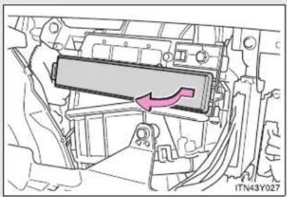
natural_image
Technical diagram of a vehicle chassis showing a highlighted component with an arrow indicating direction (no text or symbols present)▶ Right-hand drive vehicles

natural_image
Technical diagram of a vehicle engine compartment with a highlighted component and directional arrow (no text or symbols)Replacement method

text_image
ITN43Y029Remove the air conditioning filter and replace it with a new one.
The “↑UP” marks shown on the filter should be pointing up.
Cleaning method

text_image
UP ITY43C029If the filter is dirty, clean by blowing compressed air through the filter from the underside.
Hold the air gun 5 cm (2 in.) from the filter and blow for approximately 2 minutes at 500 kPa (5.0 kgf/cm ^2 or bar, 72 psi).
If an air gun is not available, have the filter cleaned by any authorized Toyota dealer or repairer, or another duly qualified and equipped professional.
- Checking interval
Inspect and replace the air conditioning filter according to the maintenance schedule. In dusty areas or areas with heavy traffic flow, early replacement may be required. (For scheduled maintenance information, please refer to the "Toyota Service Booklet" or "Toyota Warranty Booklet".)
If air flow from the vents decreases dramatically
The filter may be clogged. Check the filter and replace if necessary.
NOTICE
■ To prevent damage to the system
- When using the air conditioning system, make sure that a filter is always installed.
- When cleaning the filter, do not clean with water.
4-3. Do-it-yourself maintenance
Key battery
Replace the battery with a new one if it is discharged.
■ You will need the following items:
- Flathead screwdriver (To prevent damage to the key, cover the tip of the screwdriver with rag.)
● Small Phillips-head screwdriver - Lithium battery
Vehicles with smart entry & start system: CR1632
Vehicles without smart entry & start system: CR2016
■ Replacing the battery (vehicles with smart entry & start system)

text_image
STEP 1 ITN43A007Take out the mechanical key.

text_image
STEP 2 ITN43A008Remove the cover.
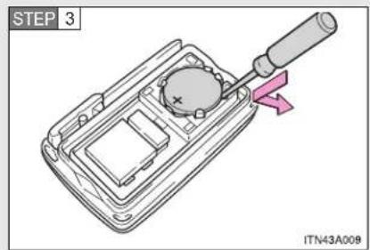
text_image
STEP 3 ITN43A008Remove the depleted battery.
Insert a new battery with the "+" terminal facing up.
■ Replacing the battery (vehicles without smart entry & start system)
▶ Type A
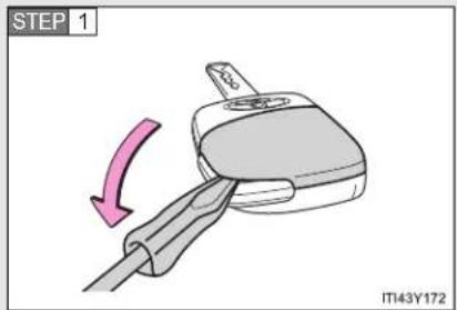
text_image
STEP 1 IT43Y172Lift the cover.
Insert the screw driver in the slot and push down.

text_image
STEP 2 IT143Y173Remove the cover.
Insert the screw driver in the bottom of the key and push down.
4-3. Do-it-yourself maintenance

text_image
STEP 3 IT143Y124Remove the depleted battery.
Insert a new battery with the "+" terminal facing up.
▶ Type B
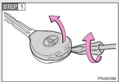
text_image
STEP 1 ITN43Y030Remove the cover.
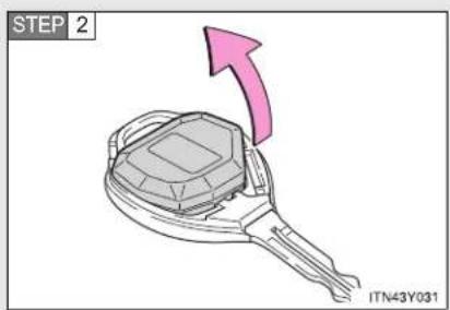
text_image
STEP 2 ITN43Y031Remove the module.

text_image
STEP 3 ITN43Y032Open the case cover using a flathead screwdriver protected with tape etc. and remove the depleted battery.
Insert a new battery with the "+" terminal facing up.
If the key battery is discharged
The following symptoms may occur.
- The smart entry & start system and wireless remote control will not function properly.
• The operational range is reduced.
■ Use the following types of lithium battery
Vehicles with smart entry & start system: CR1632
Vehicles without smart entry & start system: CR2016
- Batteries can be purchased at any authorized Toyota dealer or repairer, or another duly qualified and equipped professional, jewelers, or camera stores.
- Replace only with the same or equivalent type recommended by any authorized Toyota dealer or repairer, or another duly qualified and equipped professional.
- Dispose of used batteries according to the local laws.

CAUTION
■ Removed battery and other parts
Keep away from children. These parts are small and if swallowed by a child, they can cause choking. Failure to do so could result in death or serious injury.
■ Certification for the smart entry & start system
RISK OF EXPLOSION IF BATTERY IS REPLACED BY AN INCORRECT TYPE. DISPOSE OF USED BATTERIES ACCORDING TO THE INSTRUCTIONS.

NOTICE
For normal operation after replacing the battery
Observe the following precautions to prevent accidents.
• Always work with dry hands.
Moisture may cause the battery to rust.
- Do not touch or move any other components inside the remote control.
- Do not bend the battery terminals.
- Please perform this operation in a clean environment to avoid garbage, oil, etc. insertion in the key.
4-3. Do-it-yourself maintenance
Checking and replacing fuses
If any of the electrical components do not operate, a fuse may have blown. If this happens, check and replace the fuses as necessary.
STEP 1 Vehicles with smart entry & start system: Turn the "ENGINE START STOP" switch OFF.
Vehicles without smart entry & start system: Turn the engine switch to the "LOCK" position.
STEP 2 The fuses are located in the following places. To check the fuses, follow the instructions below.
Engine compartment
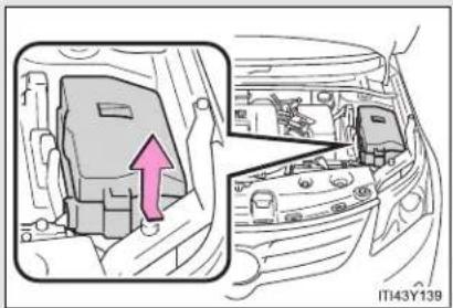
natural_image
Diagram of a car interior showing engine compartment with a pink arrow indicating direction (no text or symbols)Push the tab in and lift the lid off.
■ Under the instrument panel (left-hand drive vehicles)
▶ Driver's side instrument panel (type A)
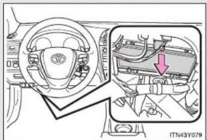
natural_image
Interior view of a car showing steering wheel, dashboard, and engine compartment with a red arrow indicating a component (no text or symbols present)Remove the lid.
4-3. Do-it-yourself maintenance
▶ Driver's side instrument panel (type B)

text_image
ITN43Y035Remove the coin box.
■ Under the instrument panel (right-hand drive vehicles)
▶ Passenger's side instrument panel (type A)
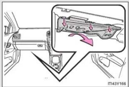
text_image
IT43Y166Remove the cover.
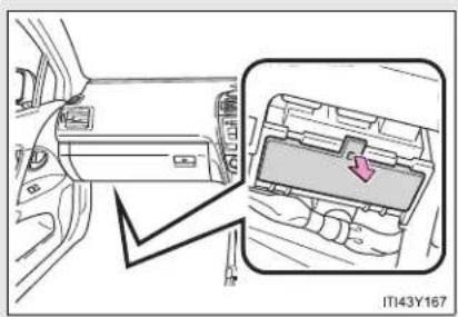
natural_image
Interior view of a car showing the dashboard and internal electronics panel (no text or symbols visible)Remove the lid.
▶ Passenger's side instrument panel (type B)
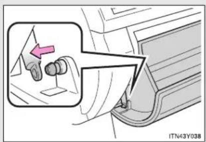
text_image
ITN43Y038Open the glove box. Slide off the damper.
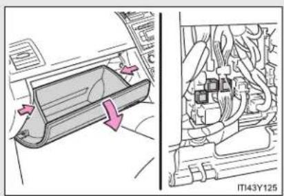
natural_image
Diagram showing a car interior with directional arrows and a close-up of internal components (no text or symbols)Push in each side of the glove box to disconnect the claws.
STEP 3 After a system failure, see "Fuse layout and amperage ratings" (→P. 574) for details about which fuse to check.
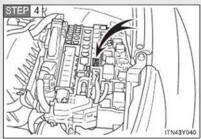
text_image
STEP 4 ITN43Y040Remove the fuse with the pull-out tool.
STEP 5 Check if the fuse has blown.
▶ Type A

natural_image
Two identical 3D component diagrams labeled 1 and 2, each with a base marked 'C0.6.2' and internal wavy lines (no text or symbols on the components themselves)1 Normal fuse
2 Blown fuse
Replace it with one of an appropriate amperage rating. The amperage rating can be found on the fuse box lid.
▶ Type B
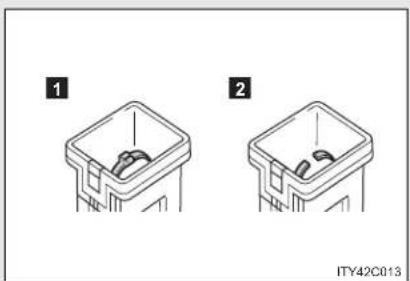
natural_image
Two identical diagrams of a plastic bin with internal components, labeled 1 and 2 (no text or symbols on the bins themselves)1 Normal fuse
2 Blown fuse
Replace it with one of an appropriate amperage rating. The amperage rating can be found on the fuse box lid.
▶ Type C
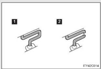
natural_image
Two identical mechanical component diagrams labeled 1 and 2, showing curved and straight ends with no text or symbols.1 Normal fuse
2 Blown fuse
Contact any authorized Toyota dealer or repairer, or another duly qualified and equipped professional.
▶ Type D
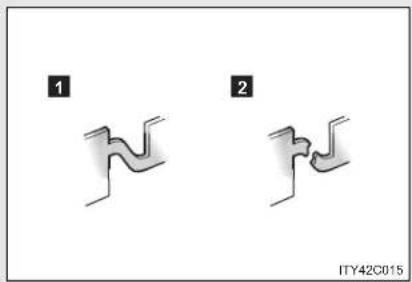
text_image
1 2 ITY42C0151 Normal fuse
2 Blown fuse
Contact any authorized Toyota dealer or repairer, or another duly qualified and equipped professional.
Fuse layout and amperage ratings
■ Engine compartment

text_image
1 2 3 4 5 6 7 8 9 10 11 12 13 [14] [15] [16] 29 30 31 32 33 34 35 37 38 39 40 41 42 36 43 44 45 46 47 48 49 50 S1 17 18 19 20 21 22 23 24 25 26 27 28 37 38 39 40 41 42 36 ITI43Y148| Fuse Ampere Circuit | |||
| 1 H | -LP CLN 30 A Headlight cleaner | ||
| 2 R | DI FAN 40 A Electric cooling fan(s) | ||
| 3 | CDS FAN | 30 A | Electric cooling fan(s)*1 |
| 4 A | BS NO.1 50 A Anti-lock brake system, VSC | ||
| 5 HFuse | TR 50 A Air conditioning systemAmpere | Circuit | |
| 6 | ALT | 120 A^*2 | RDI FAN, CDS FAN, H-LP CLN,PWR SEAT LH, FUEL OPN, ABSNO.1, ABS NO.2, FR DEICER,PSB, HTR, STV HTR, PWR OUT-LET, HTR SUB NO.1, HTR SUBNO.2, HTR SUB NO.3, ECU-IGNO.2, HTR-IG, WIPER, RRWIPER, WASHER, ECU-IG NO.1,ECU-IG NO.3, SEAT HTR, AM1,DOOR, STOP, P FR DOOR,POWER, RR DOOR, RL DOOR,OBD, ACC-B, RR FOG, FR FOG,TI & TE, SHADE, PWR SEAT RH,DEF, TAIL, DRL |
| 140 A^*1 | |||
| 7 | EPS 80 A Electric power steering | ||
| 8 | G L *1 O W | 80 A Engine glow system | |
| 9 | P - S *2Y | S 30 A VAL VERMATIC system | |
| 10 | EFI MAIN *1 | 50 A | Multiport fuel injection system/sequential multiport fuel injectionsystem, EFI NO.1, EFI NO.2 |
| 11 | P/I 50 A EFI MAIN, HORN, IG2, EDU | ||
| 12 | H-LP MAIN 50 A | H-LP LH LO, H-LP RH LO, H-LPLH HI, H-LP RH HI | |
| 13 | E-PKB 30 A Electric parking brake | ||
| 14 | PARE 10 A Spare fuse | ||
| 15 | PARE 30 A Spare fuse | ||
| 16 | $PARE 20 A Spare fuse | ||
| 17 | AMP | 30 A Audio system | |
4-3. Do-it-yourself maintenance
| Fuse Ampere | Circuit | ||
| 18 | DOOR NO.2 25 A | Power door lock system | |
| 19 | EFI MAINNO.2*1 | 7.5 A | Multiport fuel injection system/sequential multiport fuel injection system |
| 20 | ECU-B2 10 A | Smart entry & start system, air conditioning system, power windows, power seat | |
| 21 | ECU-B 10 A | Gauges and meters, main body ECU, steering sensor, wireless remote control, smart entry & start system, tilt and telescopic steering | |
| 22 | RAD NO.1 15 A | Audio system | |
| 23 | DOME 10 A | Trunk/luggage compartment light, vanity lights, front door courtesy lights, personal/interior lights, personal lights, foot lights | |
| 24 | AM2 NO.2 7.5 A | Starting system | |
| 25 | TURN-HAZ 10 A | Turn signal lights, emergency flashers | |
| 26 | ETCS *2 | 10 A | Electronic throttle control system |
| 27 | AM2 30 A Starting system | ||
| 28 | $TRG LOCK 20 A | Steering lock | system |
| Fuse Ampere Circuit | |||
| 29 | IGT/INJ*2 | 15 A | Multiport fuel injection system/sequential multiport fuel injection system, ignition system |
| EDU*1 | 20 A | Multiport fuel injection system/sequential multiport fuel injection system | |
| 30 | EFI MAIN*2 | 20 A | Multiport fuel injection system/sequential multiport fuel injection system, EFI NO.1, EFI NO.2 |
| FUEL OPN*1 | 10 A Fuel filler door opener | ||
| 31 | HORN 15 A Horn | ||
| 32 | IG2 15 A IGN, METER | ||
| 33 | HTR SUB NO.1 30 A Air conditioning system | ||
| 34 | HTR SUB NO.2 30 A Air conditioning system | ||
| 35 | HTR SUB NO.3 30 A Air conditioning system | ||
| 36 | PWR SEAT LH 30 A Power seat, lumber support | ||
| 37 | PWR OUTLET 15 A Power outlet | ||
| 38 | PSB 30 A Pre-crash seat belt | ||
| 39 | FUEL OPN *2 | 10 A Fuel filler door opener | |
| 40 | FR DEICER 20 A Windshield wiper de-icer | ||
| 41 | ABS NO.2 30 A Anti-lock brake system, VSC | ||
| 42 | STV HTR *1 | 25 A Power heater | |
4-3. Do-it-yourself maintenance
| Fuse Ampere Circuit | |||
| 43 | EFI NO.4 *1 | 30 A | Multiport fuel injection system/sequential multiport fuel injection system, EFI NO.1, EFI NO.2 |
| 44 | IG2 NO.2 7.5 A Starting system | ||
| 45 | EFI NO.2 10 A | Air intake system, air flow meter, exhaust system | |
| 46 | EFI NO.1 10 A | Multiport fuel injection system/sequential multiport fuel injection system, air flow meter, exhaust system*1 | |
| 47 | H-LP RH HI 10 A Right-hand headlight (high beam) | ||
| 48 | H-LP LH HI 10 A Left-hand headlight (high beam) | ||
| 49 | H-LP RH LO | 15 A*4 | Right-hand headlight (low beam) |
| 10 A*5 | |||
| 50 | H-LP LH LO | 15 A*4 | Left-hand headlight (low beam) |
| 10 A*5 | |||
| 51 | EFI NO.3* 3 | 7.5 A Automatic transmission | |
*1: Vehicles with diesel engine
*2: Vehicles with gasoline engine
*3: Vehicles with diesel engine and automatic transmission
*4: Vehicles with discharge headlights
*5: Vehicles without discharge headlights
■ Under the instrument panel (type A)

text_image
1 2 3 4 5 6 7 8 9 10 11 12 13 14 15 16 17 18 19 20 21 22 23 24 25 26 27 IT43Y149| Fuse Ampere Circuit | ||||
| 1 | T A I L | 1 0 A | Front position lights, tail lights, license plate lights, rear fog light, front fog lights, manual headlight leveling dial, instrument panel lights, air conditioning system switch, audio system, Multidrive or automatic transmission shift lever illumination, glove box light, airbag manual on-off system, emergency flashers, cigarette lighter, “AFS OFF” switch, speed limiter switch, electric parking brake switch, steering switch, VSC OFF switch, Toyota parking assist-sensor switch, “LKA” switch, seat heater switch, “SPORT” switch, outside rear view mirror switches, fuel filler door opener switch | |
Maintenance and care
4-3. Do-it-yourself maintenance
| Fuse Ampere | Circuit | ||
| 2 E | ECU-IG NO.3 10 A | Toyota parking assist-sensor, AFS, windshield wiper de-icer, electric parking brake, pre-crash seat belt, paddle shift switch, tilt & telescopic steering, electric power steering | |
| 3 P | FR DOOR 20 A Power windows (passenger side) | ||
| 4 R | L DOOR 20 A Power windows (rear left) | ||
| 5 R | R DOOR 20 A Power windows (rear right) | ||
| 6 S | HADE 20 A Panoramic roof shade *1 | ||
| 7 C | IG 15 A Cigarette lighter | ||
| 8 | A C C | Outside rear view mirrors, shift lock system, audio system, main body ECU, power outlet | |
| 9 M | IR HTR 10 A Outside rear view mirror defoggers | ||
| 10 T | I & TE | 30 A Tilt & telescopic steering | |
| 11 | RR FOG | 7.5 A | Rear fog light |
| 12 | IGN | Steering lock system, SRS airbag system, multiport fuel injection system/3eential multiport fuel injection system, automatic transmission *2, starting system | |
| Fuse Ampere Circuit | |||
| 13 | METER 7.5 A Gauges and meters | ||
| 14 | EAT HTR 15 A Seat heaters | ||
| 15 | HTR-IG 10 A Air conditioning system | ||
| 16 | WIPER | Windshield wipers, rain sensing^{30}A windshield wipers*1 | |
| 17 | RR WIPER 15 A Rear window wiper | ||
| 18 | WASHER | Windshield washers, rear window^{15}$ A washer*1 | |
| 19 | ECU-IG NO.1 10 A | Main body ECU, smart entry & start system, electric cooling fan(s), shift lock system, panoramic roof shade*1, auto anti-glare inside rear view mirror, anti-lock brake system, steering sensor, yaw rate & G sensor, VSC, headlight cleaner, pre-crash safety system, LKA, driver support system | |
| 20 | ECU-IG NO.2 10 A | Back-up lights, charging system, emergency flashers, rear window defogger, “PASSENGER AIRBAG” indicator, air conditioning system, AFS, rear view monitor, Toyota parking assist-sensor | |
| 21 | OBD 7.5 A On-board diagnosis | system | |
4-3. Do-it-yourself maintenance
| Fuse Ampere Circuit | |||
| 22 | STOP | Stop lights, high mounted stop-light, anti-lock brake system, VSC, multiport fuel injection system/ sequential multiport fuel injection system, automatic transmission *2, shift lock system, starting system | |
| 23 | DOOR 25 A Power door lock system | ||
| 24 | ACC-B 25 A CIG, ACC | ||
| 25 | DRL 7.5 A Daytime running light system | ||
| 26 | FR FOG 15 A Front fog lights | ||
| 27 | AM1 | Starting system, ACC, CIG, ECU-IG NO.2, HTR-IG, WIPER, RR WIPER, WASHER, ECU-IG NO.1, ECU-IG NO.3, SEAT HTR | |
*1: Wagon only
^*2 : Vehicles with diesel engine and automatic transmission
■ Under the instrument panel (type B)
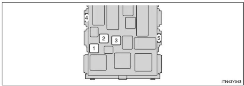
text_image
1 2 3 4 5 ITN43Y043| Fuse Ampere Circuit | |||
| 1 | POWER 30 A Power windows (driver side) | ||
| 2 | DEF 40 A Rear window defogger, MIR HTR | ||
| 3 | PWR SEAT RH 30 A Power seat, lumber support | ||
| 4 | WIPER NO.2 *1 | 7.5 A | Charging system, driver support system ECU |
| 5 | WIPER NO.2 *2 | 7.5 A | Charging system, driver support system ECU |
*1: Left-hand drive vehicle
*2: Right-hand drive vehicle
■ After a fuse is replaced
- If the lights do not turn on even after the fuse has been replaced, a bulb may need replacement. (→P. 585)
- If the replaced fuse blows again, have the vehicle inspected by any authorized Toyota dealer or repairer, or another duly qualified and equipped professional.
If there is an overload in the circuits
The fuses are designed to blow, protecting the wiring harness from damage.

CAUTION
■ To prevent system breakdowns and vehicle fire
Observe the following precautions.
Failing to do so may cause damage, and possibly a fire or injury.
- Never use a fuse of a higher amperage rating than indicated, or use any other object in place of a fuse.
● Always use a genuine Toyota fuse or equivalent.
Never replace a fuse with a wire, even as a temporary fix.
This can cause extensive damage or even fire. - Do not modify the fuse or the fuse box.

NOTICE
Before replacing fuses
Have the cause of electrical overload determined and repaired by any authorized Toyota dealer or repairer, or another duly qualified and equipped professional, as soon as possible.
4-3. Do-it-yourself maintenance
Light bulbs
You may replace the following bulbs yourself. The difficulty level of replacement varies depending on the bulb. As there is a danger that components may be damaged, we recommend that replacement is carried out by any authorized Toyota dealer or repairer, or another duly qualified and equipped professional.
■ Prepare a replacement light bulb
Check the wattage of the light bulb being replaced. (→P. 744)
■ Remove the engine compartment cover
→P. 537
Front bulb locations

text_image
Front position/daytime running light (vehicles with halogen headlight) Headlight high beam (halogen bulb) Headlight low beam (halogen bulb) Front turn signal light Front fog light (if equipped) IT143Y140■ Rear bulb locations
▶ Sedan
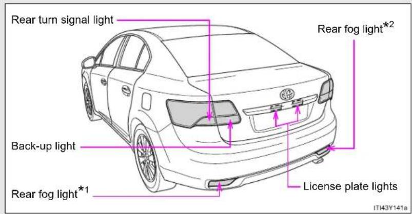
text_image
Rear turn signal light Back-up light Rear fog light*1 Rear fog light*2 License plate lights IT43Y141aWagon
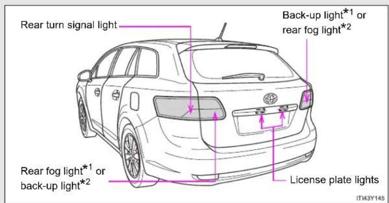
text_image
Rear turn signal light Back-up light*1 or rear fog light*2 Rear fog light*1 or back-up light*2 License plate lights IT43Y145*1: Left-hand drive vehicles
*2: Right-hand drive vehicles
Replacing light bulbs
■ Headlight low beam (vehicles with halogen bulbs)
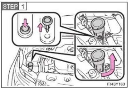
text_image
STEP 1 IT43Y163For the right side only: Remove the securing clip and turn and pull off the washer fluid filler opener.
Install the washer fluid filler opener in the reverse order of removal.
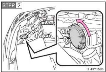
text_image
STEP 2 IT143Y150bTurn the cover counterclockwise and remove it.

text_image
STEP 3 IT143Y151aTurn the bulb base counterclockwise.
4-3. Do-it-yourself maintenance

text_image
STEP 4 IT43Y182Unplug the connector while pulling the lock release.
STEP 5 When installing, reverse the steps listed.
■ Headlight high beam (vehicles with halogen bulbs)

text_image
STEP 1 IT143Y152aTurn the cover counterclockwise and remove it.
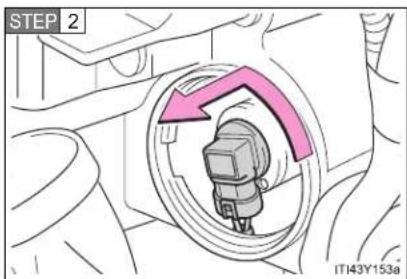
text_image
STEP 2 IT43Y153aTurn the bulb base counterclockwise.
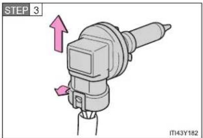
text_image
STEP 3 IT43Y182Unplug the connector while pulling the lock release.
STEP 4 When installing, reverse the steps listed.
■ Front fog light (if equipped)
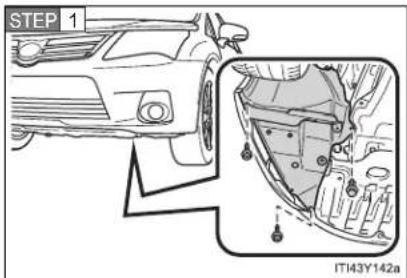
text_image
STEP 1 ITI43Y142aRemove the fender liner bolts and clip.
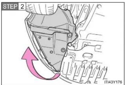
text_image
STEP 2 ITT43Y176Partly remove the fender liner.
4-3. Do-it-yourself maintenance
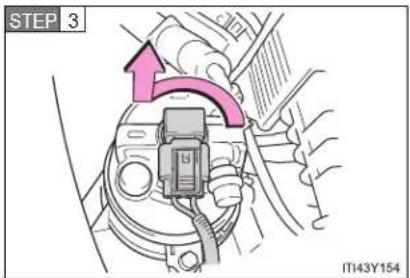
text_image
STEP 3 IT143Y154Turn the bulb base counterclockwise.

text_image
STEP 4 ITN43Y057Unplug the connector while pushing the lock release.
STEP 5 When installing, reverse the steps listed.
■ Front position/daytime running light (vehicles with halogen headlight)
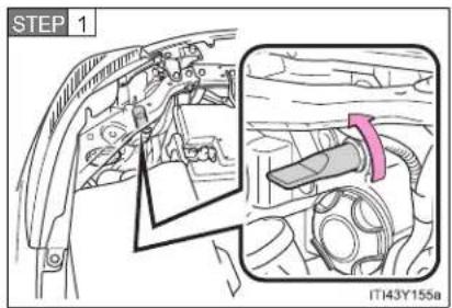
text_image
STEP 1 IT43Y155aTurn the bulb base counterclockwise.
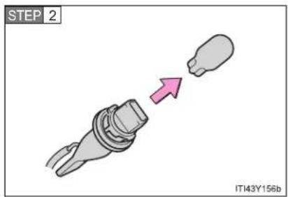
text_image
STEP 2 IT143Y156bRemove the light bulb.
STEP 3 When installing, reverse the steps listed.
■ Front turn signal light

text_image
STEP 1 IT43Y163For the right side only: Remove the securing clip and turn and pull off the washer fluid filler opener.
Install the washer fluid filler opener in the reverse order of removal.
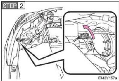
text_image
STEP 2 IT143Y157aTurn the bulb base counterclockwise.

text_image
STEP 3 ITN43Y061Remove the light bulb.
STEP 4 When installing, reverse the steps listed.
■ Back-up light (sedan)
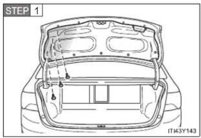
text_image
STEP 1 IT43Y143Open the trunk and remove the cover clips.

text_image
STEP 2 IT143Y180Partly remove the trunk panel cover and turn the bulb bases counterclockwise.
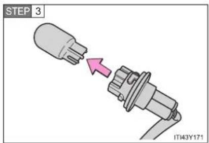
text_image
STEP 3 IT43Y171Remove the light bulb.
STEP 4 When installing, reverse the steps listed.
4-3. Do-it-yourself maintenance
■ Back-up light/rear fog light (wagon)

text_image
STEP 1 IT143Y146Open the back door and remove the cover.
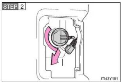
text_image
STEP 2 IT43Y181Turn the bulb bases counterclockwise.

text_image
STEP 3 IT43Y179Remove the light bulb.
STEP 4 When installing, reverse the steps listed.
■ Rear turn signal light (sedan)

text_image
STEP 1 ITN43Y067Open the trunk and remove the cover.
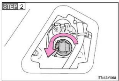
text_image
STEP 2 ITN43Y068Turn the bulb bases counterclockwise.
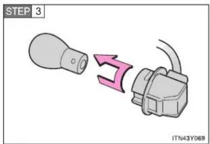
text_image
STEP 3 ITN43Y069Remove the light bulb.
STEP 4 When installing, reverse the steps listed.
4-3. Do-it-yourself maintenance
■ Rear turn signal light (wagon)

text_image
STEP 1 IT143Y147Open the back door and remove the cover.
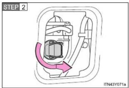
text_image
STEP 2 ITN43Y071aTurn the bulb bases counterclockwise.
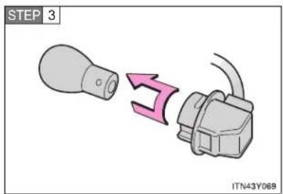
text_image
STEP 3 ITN43Y069Remove the light bulb.
STEP 4 When installing, reverse the steps listed.
■ Rear fog light (sedan)
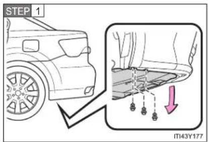
text_image
STEP 1 IT43Y177Left-hand drive vehicles:
Remove the clip and partly remove the under cover.
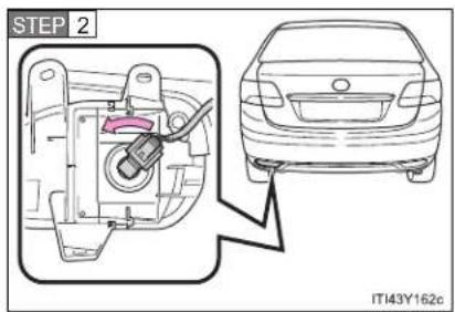
text_image
STEP 2 IT143Y162cTurn the bulb bases counterclockwise.
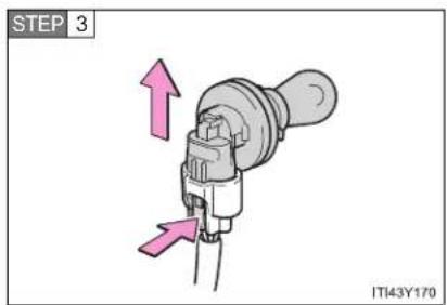
text_image
STEP 3 IT143Y170Unplug the connector while pushing the lock release.
STEP 4 When installing, reverse the steps listed.
4-3. Do-it-yourself maintenance
License plate light

text_image
STEP 1 IT43Y113aRemove the cover.
To prevent damaging the vehicle, wrap the flathead screwdriver with a tape.

text_image
STEP 2 MT43Y175Remove the light bulb.
STEP 3 When installing, reverse the steps listed.
■ Replacing the following bulbs
If any of the lights listed below has burnt out, have it replaced by any authorized Toyota dealer or repairer, or another duly qualified and equipped professional.
● Headlight low or high beams (vehicles with discharge headlights)
- Front position/daytime running lights (vehicles with discharge headlights)
- Side turn signal lights
- Stop lights
- Tail lights
● High mounted stoplight
■ When replacing the front left headlight low beam (vehicles with halogen headlight) and front left turn signal light bulbs
Remove the securing clip and the upper of the air cleaner duct to allow easy access to light bulbs.
After replacing the bulbs, make sure to firmly install the upper portion of the air cleaner duct and secure it with the clip.
- Remove the upper of the air cleaner duct
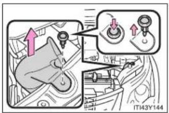
text_image
Diagram showing mechanical assembly steps with directional arrows and component labels• Installing the clip
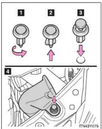
text_image
1 2 3 4 ITN43Y0751 Rotate center portion
2 Push up center portion
3 Insert
4 Press
■ Condensation build-up on the inside of the lens
Contact any authorized Toyota dealer or repairer, or another duly qualified and equipped professional, for more information in the following situations. Temporary condensation build-up on the inside of the headlight lens does not indicate a malfunction.
● Large drops of water are built up on the inside of the lens.
● Water has built up inside the headlight.
- Discharge headlights
If voltage to the discharge bulbs is insufficient, the bulbs may not come on, or may go out temporarily. The discharge bulbs will come on when normal power is restored.
LED lights
The front position/daytime running (vehicles with discharge headlights), side turn signal, stop, tail lights and high mounted stoplight consist of a number of LEDs. If any of the LEDs burn out, take your vehicle to any authorized Toyota dealer or repairer, or another duly qualified and equipped professional to have the light replaced.

CAUTION
■ Replacing light bulbs
- Turn off the headlights. Do not attempt to replace the bulb immediately after turning off the headlights. The bulbs become very hot and may cause burns.
- Do not touch the glass portion of the light bulb with bare hands. Hold the bulb by the plastic or metal portion. If the bulb is scratched or dropped, it may blow out or crack.
- Fully install light bulbs and any parts used to secure them. Failing to do so may result in heat damage, fire, or water entering the headlight unit. This may damage the headlights or cause condensation to build up on the lens.
- Do not attempt to repair or disassemble light bulbs, connectors, electric circuits or component parts. Doing so may result in death or serious injury due to electric shock.
■ Discharge headlights
- Contact any authorized Toyota dealer or repairer, or another duly qualified and equipped professional, before replacing discharge headlights (including light bulbs).
- Do not touch the high-intensity discharge headlight's high voltage socket when the headlights are turned on. An extremely high voltage of 20000 V will be discharged and could result in serious injury or death by electric shock.
■ To prevent damage or fire
Make sure bulbs are fully seated and locked.
When trouble arises
5
5-1. Essential information
Emergency flashers.... 604
If your vehicle needs to be towed....605
If you think something is wrong 615
Fuel pump shut off system (gasoline engine) 616
5-2. Steps to take in an emergency
If a warning light turns on or a warning buzzer sounds.... 617
If a warning message is displayed.... 624
If you have a flat tire (vehicles with a spare tire for sedan) 648
If you have a flat tire (vehicles with a spare tire for wagon).... 662
If you have a flat tire (vehicles without a spare tire) 676
If the engine will not start....689
If the shift lever cannot be shifted from "P" ..... 692
If the parking brake cannot be released ..... 693
If you lose your keys ...... 699
If you cannot operate the trunk opener (sedan) 700
If you cannot operate the back door opener (wagon)....701
If the electronic key does not operate properly....702
If the battery is discharged 705
If your vehicle overheats.... 710
If you run out of fuel and the engine stalls (diesel engine) 713
If the vehicle becomes stuck 714
If your vehicle has to be stopped in an emergency.... 716
603
5-1. Essential information
Emergency flashers
The emergency flashers are used to warn other drivers when the vehicle has to be stopped in the road due to a breakdown, etc.
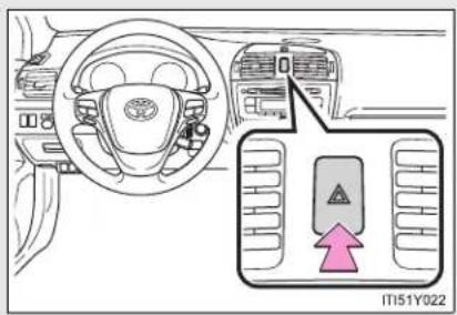
text_image
IT151Y022Press the switch.
All the turn signal lights will flash.
To turn them off press the switch once again.
Emergency flashers
If the emergency flashers are used for a long time while the engine is not operating, the battery may discharge.
5-1. Essential information
If your vehicle needs to be towed
If towing is necessary, we recommend having your vehicle towed by any authorized Toyota dealer or repairer, or another duly qualified and equipped professional, such as a commercial towing service, using a lift-type truck or a flat bed truck.
Use a safety chain system for all towing, and abide by all state/provincial and local laws.
If towing from the front, the vehicle's rear wheels and axles must be in good condition. (→P. 612)
If they are damaged, use a towing dolly or flat bed truck.
Before towing
The following may indicate a problem with your transmission. Contact any authorized Toyota dealer or repairer, or another duly qualified and equipped professional, before towing.
● The engine is running, but the vehicle will not move.
● The vehicle makes an abnormal sound.
5-1. Essential information
Emergency towing
If a tow truck is not available, in an emergency your vehicle may be temporarily towed using a cable or chain secured to the emergency towing eyelets or hook. This should only be attempted on hard, surfaced roads for short distances at low speeds.
A driver must be in the vehicle to steer and operate the brakes. The vehicle's wheels, drive train, axles, steering and brakes must be in good condition.
▶ Towing eyelets (front)
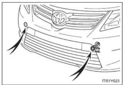
natural_image
Line drawing of a car's front grille with a logo and a key inserted, showing no text or symbols.▶ Towing hook (rear)

natural_image
Line drawing of a car's rear wheel and side-mounted sensor, showing motion blur (no text or symbols)Emergency towing procedure
▶ Vehicles with smart entry & start system
STEP 1 Release the parking brake.
STEP 2 Put the shift lever in "N".
STEP 3 The "ENGINE START STOP" switch must be in ACCESSORY mode (engine off) or IGNITION ON mode (engine running).
▶ Vehicles without smart entry & start system
STEP 1 Release the parking brake.
STEP 2 Put the shift lever in "N".
STEP 3 Put the engine switch in the "ACC" (engine off) or "ON" position (engine running).

CAUTION
■ While towing
- Use extreme caution when towing the vehicle.
Avoid sudden starts or erratic driving maneuvers which place excessive stress on the emergency towing eyelets and the cables or chains. Always be cautious of the surroundings and other vehicles while towing.
- If the engine is not running, the power assist for the brakes and steering will not function, making steering and braking more difficult.
5-1. Essential information

NOTICE
To prevent causing serious damage to the transmission (vehicles with a Multidrive or automatic transmission)
Never tow this vehicle from the rear with the front wheels on the ground. This may cause serious damage to the transmission.
■ When towing a vehicle without using a towing dolly (vehicles with a manual transmission)
Vehicles with smart entry & start system: The "ENGINE START STOP" switch must not be OFF.
Vehicles without smart entry & start system: The engine switch must not be "LOCK" position.
■ To avoid serious damage to your vehicle (vehicles with a Multidrive or automatic transmission)
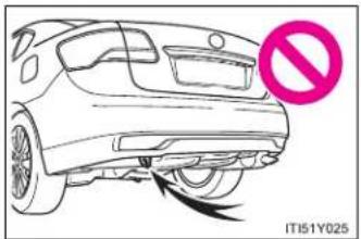
natural_image
Line drawing of a car's front wheel with a no-smoking symbol (no text or labels on the car itself)Do not use the rear emergency towing hook.
Installing towing eyelets

text_image
STEP 1 IT151Y029Remove the eyelet cover.
The eyelet cover has a rotary mechanism which allows the cover to be opened by pushing on the outer side.
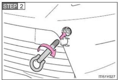
text_image
STEP 2 IT51Y027Insert the towing eyelet into the hole and tighten partially by hand.

text_image
STEP 3 IT151Y028Tighten down the towing eyelet securely using a wheel nut wrench.
5-1. Essential information
If it is difficult to push the eyelet open
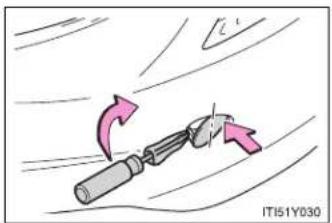
natural_image
Illustration of a tool with directional arrows indicating motion or movement (no text or symbols)A screwdriver wrapped in cloth can be used to help open the eyelet.
Put the screwdriver into the inner side of the hook cover.
■ Location of the emergency towing eyelet
→P. 648, 662, 676

CAUTION
■ Installing towing eyelets to the vehicle
Make sure that towing eyelets are installed securely. If not securely installed, towing eyelets may come loose during towing. This may lead to accidents that cause serious injury or even death.
Towing with a sling-type truck
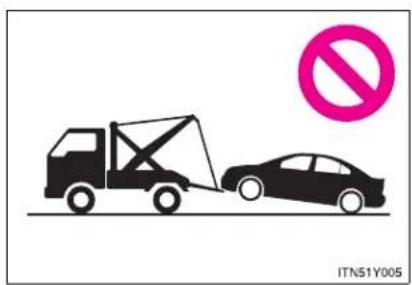
text_image
ITN51Y005
NOTICE

To prevent body damage
Do not tow with a sling-type truck, either from the front or rear.
5-1. Essential information
Towing with a wheel-lift type truck from the front
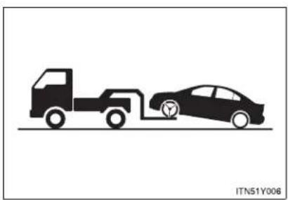
natural_image
Silhouette illustration of a truck and car with a charging plug, no text or symbols presentRelease the parking brake.
NOTICE
■ To prevent damaging the vehicle
When raising the vehicle, ensure adequate ground clearance for towing at the opposite end of the raised vehicle. Without adequate clearance, the vehicle could be damaged while being towed.
Towing with a wheel-lift type truck from the rear

natural_image
Silhouette illustration of a truck and car on a road, no text or symbols presentMultidrive or automatic transmission: Use a towing dolly under the front wheels.
Manual transmission: We recommend to use a towing dolly under the front wheels.
Vehicles with smart entry & start system: When not using a towing dolly, turn the "ENGINE START STOP" switch to ACCESSORY mode and shift the shift lever to "N".
Vehicles without smart entry & start system: When not using a towing dolly, turn the engine switch to the "ACC" position and shift the shift lever to "N".
5-1. Essential information

NOTICE
■ To prevent causing serious damage to the transmission (Multidrive or automatic transmission)
Never tow this vehicle from the rear with the front wheels on the ground.
■ To prevent damaging the vehicle (manual transmission)
Vehicles with smart entry & start system: Do not tow the vehicle with the "ENGINE START STOP" switch OFF.
Vehicles without smart entry & start system: Do not tow the vehicle with the engine switch to the "LOCK" position.
The steering lock mechanism is not strong enough to hold the front wheel straight.
Using a flat bed truck

natural_image
Silhouette of a car on a road with traffic cones and a tire, no text or symbols presentIf you use chains or cables to tie down your vehicle, the angles shaded in black must be 45^ .
Do not overly tighten the tie downs or the vehicle may be damaged.
5-1. Essential information
If you think something is wrong
If you notice any of the following symptoms, your vehicle probably needs adjustment or repair. Contact any authorized Toyota dealer or repairer, or another duly qualified and equipped professional, as soon as possible.
Visible symptoms
- Fluid leaks under the vehicle
(Water dripping from the air conditioning after use is normal.)
● Flat-looking tires or uneven tire wear - Engine coolant temperature gauge indicates that the temperature is higher than normal
Audible symptoms
● Changes in exhaust sound
● Excessive tire squeal when cornering
● Strange noises related to the suspension system
● Pinging or other noises related to the engine
■ Operational symptoms
● Engine missing, stumbling or running rough
● Appreciable loss of power
● Vehicle pulls heavily to one side when braking
● Vehicle pulls heavily to one side when driving on a level road
- Loss of brake effectiveness, spongy feeling, pedal almost touches the floor
5-1. Essential information
Fuel pump shut off system (gasoline engine)
To minimize the risk of fuel leakage when the engine stalls or an airbag inflates upon collision, the fuel pump shut off system stops supplying fuel to the engine.
Follow the procedure below to restart the engine after the system is activated.
STEP 1 Vehicles with smart entry & start system:
Turn the "ENGINE START STOP" switch to ACCESSORY mode or OFF.
Vehicles without smart entry & start system:
Turn the engine switch to the "ACC" or "LOCK" position.
STEP 2 Restart the engine.
NOTICE
Before starting the engine
Inspect the ground under the vehicle.
If you find that fuel has leaked on to the ground, the fuel system has been damaged and is in need of repair. Do not restart the engine.
5-2. Steps to take in an emergency
If a warning light turns on or a warning buzzer sounds...
Calmly perform the following actions if any of the warning lights turn on or flash. If a light turns on or flashes, but then turns off, this does not necessarily indicate a malfunction in the system.
Stop the vehicle immediately. Continuing to drive the vehicle may be dangerous.
The following warning indicates a possible problem in the brake system. Immediately stop the vehicle in a safe place and contact any authorized Toyota dealer or repairer, or another duly qualified and equipped professional.
| Warning light | Warning light/Details |
| Brake system warning light (red indicator)Low brake fluidMalfunction in the electronically controlled brake system |
Stop the vehicle immediately.
The following warning indicates the possibility of damage to the vehicle that may lead to an accident. Immediately stop the vehicle in a safe place and contact any authorized Toyota dealer or repairer, or another duly qualified and equipped professional.
| Warning light Warning light/Details | |
| Charging system warning lightIndicates a malfunction in the vehicle's charging system. | |
Have the vehicle inspected immediately.
Failing to investigate the cause of the following warnings may lead to the system operating abnormally and possibly cause an accident. Have the vehicle inspected by any authorized Toyota dealer or repairer, or another duly qualified and equipped professional, immediately.
Warning light Warning light/Details
Malfunction indicator lamp
• The electronic engine control system;
• The electronic throttle control system;
- The electronic Multidrive or automatic transmission control system. (if equipped)
SRS warning light
• The ABS;
• The brake assist system
Brake system warning light (yellow indicator)
- The electronically controlled brake system; or
• The electric parking brake
| Warning light Warning light/Details | |
 | Electric power steering warning lightIndicates a malfunction in the EPS (Electric Power Steering) system. |
 ( ( | “PCS” warning light (if equipped)Indicates a malfunction in the PCS (Pre-Crash Safety system).The warning light will operate as follows, even when the system is not malfunctioning:The light will flash quickly when the system is operating.(→P. 333)The light will turn on when the pre-crash braking is disabled. (→P. 334)The light will turn on when the system cannot temporarily be used. (→P. 634) |
 (Flashes) (Flashes) | “AFS OFF” indicator light (if equipped)Indicates a malfunction in the AFS (Adaptive Front-lighting System). |
 | Slip indicator lightIndicates a malfunction in:VSC; orTRC |
 (Flashes) (Flashes) | “LKA” indicator light (if equipped)Indicates a malfunction in the LKA (Lane-Keeping Assist).→P. 318 |
5-2. Steps to take in an emergency
| Warning light Warning light/Details | |
 ( ( | Cruise control indicator light (if equipped)Indicates a malfunction in the cruise control system.→P. 275 |
 ( ( | Dynamic radar cruise control indicator light (if equipped)Indicates a malfunction in the dynamic radar cruise control system.→P. 281 |
 ( ( | Speed limiter indicator light (if equipped)Indicates a malfunction in the speed limiter system.→P. 300 |
Electric power steering warning light
When the battery is low or when the voltage drops temporarily, the electric power steering warning light may come on.

CAUTION
■ When the electric power steering warning light comes on
The steering wheel may become extremely heavy. If the steering wheel becomes heavier than usual when operating, firmly hold and operate it using more force than usual.
Follow the correction procedures.
After taking the specified steps to correct the suspected problem, check that the warning light turns off.
| Warning light | Warning light/Details Correction procedure | |
 | Low fuel level warning lightIndicates that remaining fuel is about 9.0 L (2.8 gal., 2.0 Imp.gal.) or less | Refuel the vehicle. |
 | Seat belt reminder light (warning buzzer)*1Warns the driver and/or front passenger to fasten their seat belts. | Fasten the seat belt.If the front passenger's seat is occupied, the front passenger's seat belt also needs to be fastened to make the warning light (warning buzzer) off. |
 | Parking brake indicator light (warning buzzer)*2Warns the driver to release parking brake. | Release the parking brake. |
5-2. Steps to take in an emergency
| Warning light | Warning light/Details Correction procedure | |
 | Master warning lightThe warning light comes on or flashes (Sometimes a buzzer may sound.) to indicate that the master warning system has detected a malfunction. | Take appropriate action in accordance with the message displayed on the multi-information display. |
*1:Driver's and front passenger's seat belt reminders:
The driver's and front passenger's seat belts reminder sounds to alert the driver and front passenger that his/her seat belt is not fastened. The buzzer sounds for 30 seconds after the vehicle has reached a speed of at least 20 km/h (12 mph). Then, if the seat belt is still unfastened, the buzzer will sound in a different tone for 90 more seconds.
*2: Parking brake engaged warning buzzer:
A buzzer will sound if the vehicle is driven at a speed of approximately 5 km/h (3 mph) or more.
■ If the malfunction indicator lamp comes on while driving
For some models, the malfunction indicator lamp will come on if the fuel tank becomes completely empty. If the fuel tank is empty, refuel the vehicle immediately. The malfunction indicator lamp will go off after several trips.
If the malfunction indicator lamp does not go off, contact any authorized Toyota dealer or repairer, or another duly qualified and equipped professional.
■ Front passenger detection sensor, seat belt reminder and warning buzzer
- If luggage is placed on the front passenger seat, the front passenger detection sensor may cause the warning light to flash and the warning buzzer to sound even if a passenger is not sitting in the seat.
- If a cushion is placed on the seat, the sensor may not detect a passenger, and the warning light may not operate properly.
5-2. Steps to take in an emergency
If a warning message is displayed
If a warning is shown on the multi-information display, stay calm and perform the following actions:

text_image
1 2 ITN52Y001a1 Master warning light
The master warning light also comes on or flashes in order to indicate that a message is currently being displayed on the multi-information display.
2 Multi-information display
If any of the warning light comes on again after the following actions have been performed, contact any authorized Toyota dealer or repairer, or another duly qualified and equipped professional.
Stop the vehicle immediately.
A buzzer sounds and a warning message is shown on the multi-information display. The following warning indicates the possibility of damage to the vehicle that may lead to an accident. Immediately stop the vehicle in a safe place and contact any authorized Toyota dealer or repairer, or another duly qualified and equipped professional.
Warning message Details


Indicates abnormal engine oil pressure
The warning light may come on if the engine oil pressure is too low.
5-2. Steps to take in an emergency
Have the vehicle inspected immediately.
A buzzer sounds and a warning message is shown on the multi-information display. Failure to investigate the cause of the following warnings may lead to the system operating abnormally and possibly cause an accident. Have the vehicle inspected by any authorized Toyota dealer or repairer, or another duly qualified and equipped professional immediately.
| Warning message Details | |
 | Indicates that the automatic transmission fluid temperature is too highStop the vehicle in a safe place, shift the shift lever to P and wait until the light goes off. If the light goes off, you may start the vehicle again. |
 (If equipped) (If equipped) | |
 | Indicates a malfunction in the steering lock system |
 (If equipped) (If equipped) | |
 | Indicates a malfunction in the emergency brake signal |
 | |
| Indicates a malfunction in the pre-crash safety system | |
| Indicates a malfunction in the radar cruise control systemPress the “ON-OFF” button once to deactivate the system, and then press the button again to reactivate the system. | |
| Indicates a malfunction in the cruise control systemPress the “ON-OFF” button once to deactivate the system, and then press the button again to reactivate the system. | |
5-2. Steps to take in an emergency
| Warning message Details | |
 | |
 | |
 | |
 | |
 (Flashes) (Flashes) | |
 | |
| (If equipped) | |
 | |
 (Flashes) (Flashes) | |
 | |
| (If equipped) | |
| CHECKCLUTCH SWITCH(If equipped) | Indicates a malfunction in the clutch switch |
| PARKING BRAKEINOPERABLE(Flashes) | Indicates that the electric parking brake system cannot complete a request |
| CHECKPARKING BRAKESYSTEM(Yellow) | Indicates a malfunction in the electric parking brake system |
| DRAIN WATERFROM FUEL FILTER(Diesel engine) | Indicates that the amount of accumulated water in the fuel filter has reached the specified level (→P. 550) |
5-2. Steps to take in an emergency
Follow the correction procedures.
A buzzer sounds and a warning message is shown on the multi-information display. After taking the specified steps to correct the suspected problem, check that the warning message goes off.
| Warning message Details Correction procedure | ||
 | Indicates that one or more of the doors is not fully closedThe system also indicates which doors are not fully closed.If the vehicle reaches a speed of 5 km/h (3 mph), [IMAGE]and a buzzer sounds to indicate that the door(s) are not yet fully closed. | Make sure that all the doors are closed.flashes |
► Sedan ► Wagon ► Wagon | Indicates that the trunk (sedan) or back door (wagon) is not fully closedThe system also indicates that the trunk (sedan) or back door (wagon) is not fully closed. If the vehicle reaches a speed of 5 km/h (3 mph),flashes and a buzzer sounds to indicate that the trunk (sedan) or back door (wagon) is not yet fully closed. | Close the trunk (sedan) or back door (wagon). |
5-2. Steps to take in an emergency
| Warning message Details Correction procedure | ||
 | Indicates that the parking brake is still engagedIf the vehicle reaches a speed of 5 km/h (3 mph), message is displayed and a buzzer sounds to indicate that the parking brake is still engaged. | |
 (Flashes) (Flashes) | ||
 | Indicates that the parking brake system is not currently functional | |
 (Flashes) (Flashes) | ||
 (Flashes) (Flashes) | ||
 | Indicates that engine oil level is low | |
 | ||
| OIL MAINTENANCE REQUIRED SOON(Diesel engine) | Vehicles with DPF catalytic converter:Indicates that the engine oil is scheduled to be changedComes on approximately 25000 km (15000 miles) after the engine oil is changed.Vehicles without DPF catalytic converter:You have forgotten to reset the oil change systemChange the engine oil in accordance with the maintenance schedule. | Check the engine oil and change if necessary. After changing the engine oil, the oil change system should be reset. (→P. 541)(The indicator will not work properly unless the oil maintenance data has been reset.) |
| OIL MAINTENANCE REQUIRED(Diesel engine) | Indicates that the engine oil and oil filter should be changed | Have the engine oil and oil filter checked and/or changed by any authorized Toyota dealer or repairer, or another duly qualified and equipped professional. After changing the engine oil, the oil change system should be reset.(→P. 541) |
5-2. Steps to take in an emergency
| Warning message Details Correction procedure | ||
 (Diesel engine) (Diesel engine) | Indicates the resetting of the engine oil maintenance system | After changing the engine oil, the oil change system should be reset. (→P. 541) |
  (If equipped) (If equipped) | Indicates that the pre-crash safety system is not currently functional | Clean the grill and the sensor if they are dirty.In case of overheating, the system will become functional once the system cools down. |
   (If equipped) (If equipped) | Indicates that the radar cruise control sensor is dirty or covered with iceIndicates that the radar cruise control system is unable to judge vehicle-to-vehicle distance | Clean the grill and the sensor if they are dirty.If the windshield wipers are on, turn them off or set them to a mode other than “AUTO” or high speed wiper operation. |
  (If equipped) (If equipped) | ||
 | Indicates that the lane keeping assist system is not available | LKA is not available when the following condition is detected. The function can be resumed when the following condition disappears and the LKA switch is turned off and then on.• The temperature of the camera is too high or too low.• The decline of EPS performance. |
 (If equipped) (If equipped) | ||
5-2. Steps to take in an emergency
| Warning message Details Correction procedure | ||
 (Flashes)(If equipped) (Flashes)(If equipped) | Indicates that there is a possibility of a frontal collision | Slow the vehicle by applying the brakes. |
  (Flashes)(If equipped) (Flashes)(If equipped) | Indicates that there is a high possibility of a frontal collision, or that the pre-crash braking function is operating | Slow the vehicle by applying the brakes. |
  (Flashes) (Flashes) | Indicates that the headlight have been left on | Turn off the headlights. |
Have the malfunction repaired immediately. (Vehicles with smart entry & start system)
After taking the specified steps to correct the suspected problem, check that the warning message and light go off.
| Interior buzzer | Exterior buzzer | Warning message Details | Correction procedure | |
| Sounds once | — |   (Flashes) (Flashes) | The electronic key is not detected when an attempt is made to start the engine. | Confirm the location of the electronic key. |
5-2. Steps to take in an emergency
| Interior buzzer | Exterior buzzer | Warning message Details | Correction procedure | |
| Sounds once | Sounds 3 times |   (Flashes) (Flashes) | The electronic key was carried outside the vehicle and a door other than the driver's door was opened and closed while the "ENGINE START STOP" switch was in a mode other than off. | Bring the electronic key back into the vehicle. |
| The driver's door was opened and closed while the electronic key was not in the vehicle, the shift lever was in P (Multidrive or automatic transmission) or N (manual transmission) and the "ENGINE START STOP" switch was not turned off. | Turn the "ENGINE START STOP" switch off or bring the electronic key back into the vehicle. | |||
| Sounds once | Sounds once for 10 seconds |   (Displayed alternately) (Displayed alternately)  (Flashes) (Flashes) | Turn the “ENGINE START STOP” switch off and lock the doors again. | |
| Sounds once | — |   (Flashes) (Flashes) | Confirm that the electronic key is inside the vehicle. | |
5-2. Steps to take in an emergency
| Interior buzzer | Exterior buzzer | Warning message Details | Correction procedure | |
| Continuous | — | SHIFT TOP POSITION(Flashes)(Multidrive or automatic transmission) | The driver's door was opened when the shift lever was not in P and the “ENGINE START STOP” switch was not turned off. | Shift the shift lever to P. |
| Continuous | Continuous | SHIFT TOP POSITIONKEY NOT DETECTED(Displayed alternately)(Flashes)(Multidrive or automatic transmission) | The driver's door was opened and closed while the electronic key was not in the vehicle, the shift lever was not in P and the “ENGINE START STOP” switch was not turned off. | Shift the shift lever to P.Bring the electronic key back into the vehicle. |
| Sounds once | Continuous |  | An attempt was made to lock the doors using the smart entry & start system while the electronic key was still inside the vehicle. | |
 (Flashes) (Flashes) | An attempt was made to lock either front door by opening a door and putting the inside lock button into the lock position, then closing the door by pulling on the outside door handle with the electronic key still inside the vehicle. | |||
5-2. Steps to take in an emergency
| Interior buzzer | Exterior buzzer | Warning message Details | Correction procedure | |
| Sounds once | — |  (Multidrive or automatic transmission)or (Multidrive or automatic transmission)or (Manual transmission) (Manual transmission) (Flashes) (Flashes) | ·When the doors were unlocked with the mechanical key and then the “ENGINE START STOP” switch was pressed, the electronic key could not be detected in the vehicle.·The electronic key could not be detected in the vehicle even after the “ENGINE START STOP” switch was pressed two consecutive times. | Touch the electronic key to the “ENGINE START STOP” switch while depressing the brake pedal (Multidrive or automatic transmission) or clutch pedal (manual transmission). |
| Sounds once | — |  | Shift the shift lever to P and start the engine. | |
 (Flashes) (Multidrive or automatic transmission) (Flashes) (Multidrive or automatic transmission) | ||||
| Sounds once | — |  | To turn off the engine, first shift the shift lever to P and then turn the “ENGINE START STOP” switch off. | |
 (Flashes) (Multidrive or automatic transmission) (Flashes) (Multidrive or automatic transmission) | ||||
(Multidrive or automatic transmission)
5-2. Steps to take in an emergency
| Interior buzzer | Exterior buzzer | Warning message Details | Correction procedure | |
| — | — | AUTO POWER OFF TO CONSERVE BATTERY | Power was turned off due to the automatic power off function. | Next time when starting the engine, increase the engine speed slightly and maintain that level for approximately 5 minutes to recharge the battery. |
| Sounds once | — | KEY BATTERY LOW | The electronic key has a low battery. (The message will be shown for about 15 seconds.) | Replace the electronic key battery. (→P. 564) |
| Sounds once | — | The driver's door was opened and closed with the “ENGINE START STOP” switch turned off and then the “ENGINE START STOP” switch was put in ACCESSORY mode twice without the engine being started. | Press the “ENGINE START STOP” switch while depressing the brake pedal (Multidrive or automatic transmission) or clutch pedal (manual transmission). | |
| During an engine starting procedure in the event that the electronic key was not functioning properly (→P. 702), the “ENGINE START STOP” switch was touched with the electronic key. | Press the “ENGINE START STOP” switch within 10 seconds of the buzzer sounding. | |||
5-2. Steps to take in an emergency
| Interior buzzer | Exterior buzzer | Warning message Details | Correction procedure | |
| Sounds once | — |   (Flashes) (Flashes) | The steering lock could not be released within 3 seconds of the “ENGINE START STOP” switch being pressed. | Press the “ENGINE START STOP” switch while depressing the brake pedal and moving the steering wheel left and right. |
■ Warning light display in radar cruise mode (if equipped)
In the following cases, the warning light may not be displayed even if vehicle-to-vehicle distance decreases:
- When your vehicle and the vehicle ahead are traveling at the same speed or the vehicle ahead is traveling more quickly than your vehicle
- When the vehicle ahead is traveling at a very low speed
- Immediately after cruise control speed is set
- At the instant the accelerator pedal is depressed
■ After changing the engine oil (Diesel engine)
Make sure to reset the oil maintenance data. (→P. 541)
NOTICE
■ While the engine oil level warning is displayed
Continued engine operation with low engine oil will damage the engine.
■ Engine oil maintenance message (diesel engine)
The warning message is based on the projected driving range after engine oil maintenance message is reset.
The system does not monitor the purity of the engine oil.
If the "DRAIN WATER FROM FUEL FILTER" warning message is displayed (diesel engine)
Never drive the vehicle if the warning message is displayed. Continued driving with water accumulated in the fuel filter will damage the fuel injection pump.
5-2. Steps to take in an emergency
If you have a flat tire (vehicles with a spare tire for sedan)
Remove the flat tire and replace it with the spare provided.
Before jacking up the vehicle
- Stop the vehicle on a hard, flat surface.
- Set the parking brake.
- Shift the shift lever to "P" (Multidrive or automatic transmission) or "R" (manual transmission).
- Stop the engine.
● Turn on the emergency flashers. (→P. 604)
■ Location of the spare tire, jack and tools
▶ Vehicles with a compact spare tire
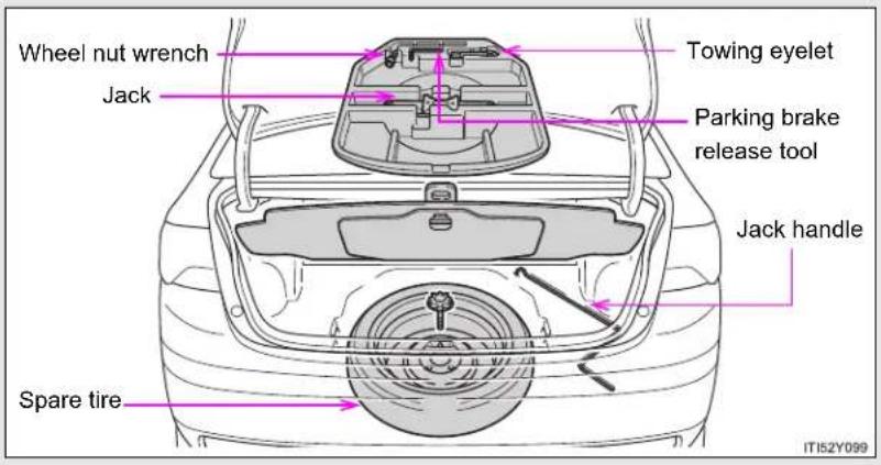
text_image
Wheel nut wrench Jack Towing eyelet Parking brake release tool Jack handle Spare tire IT152Y099▶ Vehicles with a standard spare tire
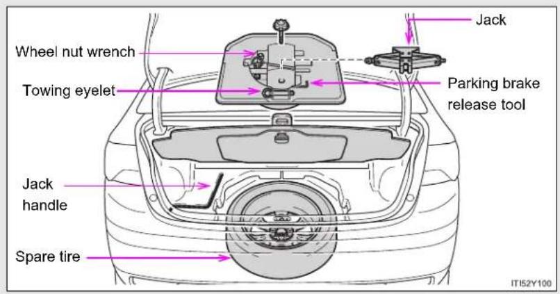
text_image
Wheel nut wrench Towing eyelet Jack Packing brake release tool Jack handle Spare tire IT152Y1005-2. Steps to take in an emergency
Taking out the jack

text_image
STEP 1 ITI52Y101Lift up the hook of the panel on the trunk floor.
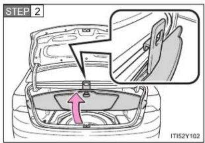
text_image
STEP 2 IT152Y102Secure the panel using the hook provided.
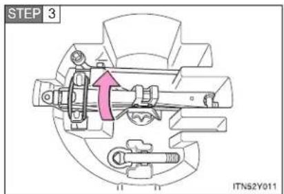
text_image
STEP 3 ITN52Y011Vehicles with a standard spare tire:
Unhook the tightening strap and remove the jack.
After storing the jack, make sure it is securely held by the tightening strap.
Taking out the spare tire
▶ Vehicles with a compact spare tire
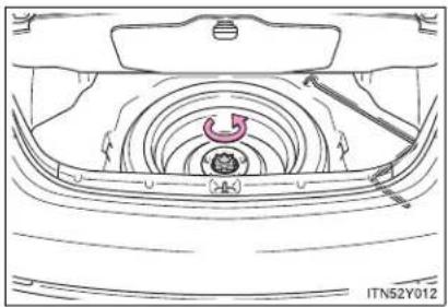
natural_image
Technical line drawing of a car interior showing internal components and airflow path (no text or symbols)Loosen the center fastener that secures the spare tire.
▶ Vehicles with a standard spare tire

natural_image
Technical diagram of a car suspension system showing wheel, gear, and dashboard components (no text or labels)Loosen the center fastener that secures the spare tire and tool box.
5-2. Steps to take in an emergency
Replacing a flat tire

natural_image
Line drawing of a sedan with exhaust plume, no text or symbols presentChock the tires.
| Flat tire Wheel chock | positions | |
| Front | Left-hand side Behind the rear right-hand side tire | |
| Right-hand side Behind the rear left-hand side tire | ||
| Rear | Left-hand side In front of the front right-hand side tire | |
| Right-hand side In front of the front left-hand side tire | ||

text_image
STEP 2 ITN52Y015Vehicles with a steel wheel, remove the wheel ornament using the wrench.
To protect the wheel ornament, place a rag between the wrench and the wheel ornament, as shown in the illustration.
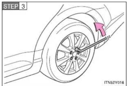
text_image
STEP 3 ITN52Y016Slightly loosen the wheel nuts (one turn).
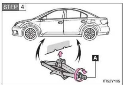
text_image
STEP 4 A IT152Y105Turn the tire jack portion "A" by hand until the notch of the jack is in contact with the jack point.
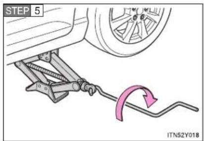
text_image
STEP 5 ITN52Y018Raise the vehicle until the tire is slightly raised off the ground.

natural_image
Illustration of hands holding a tire on a car wheel, no text or symbols presentRemove all the wheel nuts and the tire.
When resting the tire on the ground, place the tire so that the wheel design faces up to avoid scratching the wheel surface.
5-2. Steps to take in an emergency
Installing the spare tire
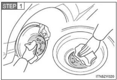
text_image
STEP 1 ITN52Y020Remove any dirt or foreign matter from the wheel contact surface.
If foreign matter is on the wheel contact surface, the wheel nuts may loosen while the vehicle is in motion, and the tire may come off the vehicle.
STEP 2 Install the tire and loosely tighten each wheel nut by hand by approximately the same amount.
▶ Replacing a steel wheel with a steel wheel (including a compact spare tire)
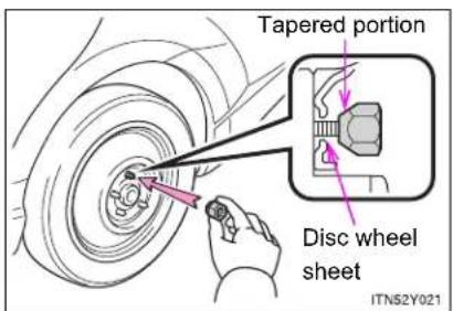
text_image
Tapered portion Disc wheel sheet ITN52Y021Tighten the nuts until the tapered portion comes into loose contact with the disc wheel sheet.
▶ Replacing an aluminum wheel with a steel wheel (including a compact spare tire)

text_image
Tapered portion Disc wheel sheet ITN52Y022Tighten the nuts until the tapered portion comes into loose contact with the disc wheel sheet.
▶ Replacing an aluminum wheel with an aluminum wheel

text_image
Disc wheel Washer ITN52Y023Turn the nut washers until they come into contact with the disc wheel.

text_image
STEP 3 ITN52Y024Lower the vehicle.
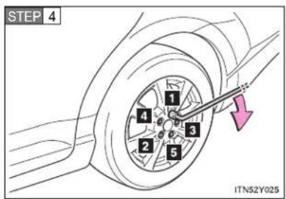
text_image
STEP 4 1 2 3 4 5 ITN52Y025Firmly tighten each nut two or three times in the order shown in the illustration.
Tightening torque:
103 N·m (10.5 kgf·m, 76 ft·lbf)
5-2. Steps to take in an emergency
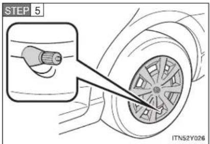
text_image
STEP 5 ITN52Y026Vehicles with a steel wheel, rein- stall the wheel ornament.
Align the cutout of the wheel ornament with the valve stem as shown.
STEP 6 Stow the flat tire, tire jack and all tools.
The compact spare tire
- The compact spare tire is identified by the label "TEMPORARY USE ONLY" on the tire sidewall. Use the compact spare tire temporarily only in an emergency.
- Make sure to check the tire inflation pressure of the compact spare tire. (→P. 739)
■ If you have a flat front tire on a road covered with snow or ice
Install the compact spare tire on the rear of the vehicle. Perform the following steps and fit tire chains to the front tires.
STEP 1 Replace a rear tire with the compact spare tire.
STEP 2 Replace the flat front tire with the tire removed from the rear of the vehicle.
STEP 3 Fit tire chains to the front tires.
■ Certification for the jack
CE
Manufacturer's Declaration of Conformity
Manufacturer :
ARIKAN KRİKO A.Ş
Organize Sanayi Bölgesi 2.Cd.26110 ESKİŞEHİR / TURKEY
The EU Directives covered by this Declaration
2006 / 42 / EC Machinery Directive
The product covered by this declaration
JACK SUB-ASSY. PANTOGRAPH
model
0.8 ton, 1.1 ton
The basis on which conformity is being declared
The product identified above complies with the requirements of the Machinery Directive
Directive above by meeting following standards
857-ISO 8720
The technical documentation required to demonstrate that the product meets the requirement the Machinery Directive has been compiled by the signatory below and is available for inspection by the relevant enforcement authorities.
A sample of the product has been tested by the manufacturer
Technical File No:2010-TOYOTA JACK-ISO8720-1
The CE mark was first applied in:2010
Done at Shizuoka, Japan
Signature

Date of Issue : 24.08.2010
5-2. Steps to take in an emergency

CAUTION
■ Using the tire jack
Improper use of the tire jack may lead to death or serious injuries due to the vehicle suddenly falling off the jack.
- Do not use the tire jack for any purpose other than replacing tires or installing and removing tire chains.
- Only use the tire jack that comes with this vehicle for replacing a flat tire. Do not use it on other vehicles, and do not use other tire jacks for replacing tires on this vehicle.
● Always check that the tire jack is securely set to the jack point. - Do not put any part of your body under the vehicle supported by a jack.
- Do not start or run the engine while your vehicle is supported by the jack.
- Do not raise the vehicle while someone is in it.
- When raising the vehicle, do not put an object on or under the jack.
- Do not raise the vehicle to a height greater than that required to replace the tire.
Use a jack stand if it is necessary to get under the vehicle.
Take particular care when lowering the vehicle to ensure that no one working on or near the vehicle will be injured.

CAUTION
■ Replacing a flat tire
- Observe the following precautions.
Failure to do so may result in serious injury:
- Do not try to remove the wheel ornament by hand. Take due care in handling the ornament to avoid unexpected personal injury.
- Do not attach a heavily damaged wheel ornament, as it may fly off the wheel while the vehicle is moving.
- Failure to follow these precautions could cause the wheel nuts to loosen and the tire to fall off, resulting in death or serious injury.
- Have the wheel nuts tightened with a torque wrench to 103 N·m (10.5 kgf·m, 76 ft·lbf) as soon as possible after changing wheels.
Failure to follow these precautions could cause the nuts to loosen and the wheel may fall off, which could lead to an accident causing death or serious injury. - When installing the wheel nuts, be sure to install the wheel nuts with the tapered ends facing inward. (→P. 559)
When using the standard spare tire (vehicles with a spare tire of different wheel type from the installed tires)
- Replace the standard spare tire with a standard tire as soon as possible.
- Avoid sudden acceleration, deceleration and braking, as well as sharp cornering.
■ When using the compact spare tire
- Remember that your compact spare tire is specifically designed for use with your vehicle. Do not use your compact spare tire on another vehicle.
- Do not use two compact spare tires simultaneously.
- Replace the compact spare tire with a standard tire as soon as possible.
- Avoid sudden acceleration, deceleration and braking, as well as sharp cornering.
5-2. Steps to take in an emergency

CAUTION
■ Speed limit when using the compact spare tire
Do not drive at speeds in excess of 80 km/h (50 mph) when a compact spare tire is installed on the vehicle.
The compact spare tire is not designed for driving at high speeds. Failing to observe this precaution may lead to an accident.
■ When the spare tire is installed
The vehicle speed may not be correctly detected, and the following systems may not operate correctly:
• ABS & brake assist
VSC
TRC
• Navigation system (if equipped)
Toyota parking assist-sensor (if equipped)
• Dynamic radar cruise control (if equipped)
• Cruise control (if equipped)
• PCS (if equipped)
LKA (if equipped)
• AFS (if equipped)

NOTICE
Do not drive the vehicle with a flat tire
Do not continue driving with a flat tire.
Driving even a short distance with a flat tire can damage the tire and the wheel beyond repair.
- Be careful when driving over bumps with the compact spare tire installed on the vehicle
The vehicle becomes lower when driving with the compact spare tire compared to when driving with standard tires. Be careful when driving over uneven road surfaces.
- Driving with tire chains and the compact spare tire
Do not fit tire chains to the compact spare tire.
Tire chains may damage the vehicle body and adversely affect driving performance.
5-2. Steps to take in an emergency
If you have a flat tire (vehicles with a spare tire for wagon)
Remove the flat tire and replace it with the spare provided.
Before jacking up the vehicle
- Stop the vehicle on a hard, flat surface.
- Set the parking brake.
- Shift the shift lever to "P" (Multidrive or automatic transmission) or "R" (manual transmission).
- Stop the engine.
● Turn on the emergency flashers. (→P. 604)
■ Location of the spare tire, jack and tools
▶ Vehicles with a compact spare tire

text_image
Towing eyelet Wheel nut wrench Parking brake release tool Jack Spare tire Rear auxiliary box Jack handle IT152Y116▶ Vehicles with a standard spare tire

text_image
Jack Rear auxiliary box Jack handle Wheel nut wrench Towing eyelet Parking brake release tool Spare tire IT152Y1175-2. Steps to take in an emergency
Taking out the jack

text_image
STEP 1 IT152Y115Remove the rear deck board.
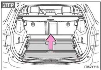
text_image
STEP 2 IT152Y118Remove the rear auxiliary box.

text_image
STEP 3 ITN52Y011Vehicles with a standard spare tire:
Unhook the tightening strap and remove the jack.
After storing the jack, make sure it is securely held by the tightening strap.
Taking out the spare tire
▶ Vehicles with a compact spare tire
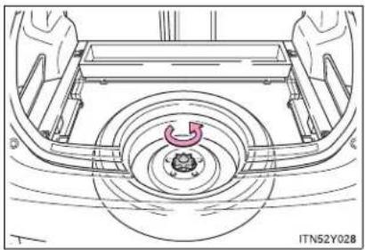
natural_image
Technical line drawing of a car wheel assembly with no visible text or symbolsLoosen the center fastener that secures the spare tire.
▶ Vehicles with a standard spare tire
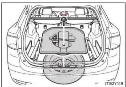
natural_image
Top-down technical illustration of a car's rear engine compartment showing internal components and structural details (no text or symbols)Loosen the center fastener that secures the spare tire and tool box.
5-2. Steps to take in an emergency
Replacing a flat tire

natural_image
Line drawing of a car with exhaust airflow and no text or symbolsChock the tires.
| Flat tire Wheel chock | positions | |
| Front | Left-hand side Behind the rear right-hand side tire | |
| Right-hand side Behind the rear left-hand side tire | ||
| Rear | Left-hand side In front of the front right-hand side tire | |
| Right-hand side In front of the front left-hand side tire | ||

text_image
STEP 2 ITN52Y015Vehicles with a steel wheel, remove the wheel ornament using the wrench.
To protect the wheel ornament, place a rag between the wrench and the wheel ornament, as shown in the illustration.

text_image
STEP 3 ITN52Y016Slightly loosen the wheel nuts (one turn).
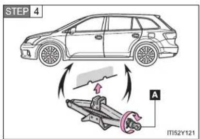
text_image
STEP 4 A IT152Y121Turn the tire jack portion "A" by hand until the notch of the jack is in contact with the jack point.

text_image
STEP 5 ITN52Y018Raise the vehicle until the tire is slightly raised off the ground.

natural_image
Illustration of hands installing or adjusting a tire on a car wheel (no text or symbols)Remove all the wheel nuts and the tire.
When resting the tire on the ground, place the tire so that the wheel design faces up to avoid scratching the wheel surface.
5-2. Steps to take in an emergency
Installing the spare tire

text_image
STEP 1 ITN52Y020Remove any dirt or foreign matter from the wheel contact surface.
If foreign matter is on the wheel contact surface, the wheel nuts may loosen while the vehicle is in motion, and the tire may come off the vehicle.
STEP 2 Install the tire and loosely tighten each wheel nut by hand by approximately the same amount.
▶ Replacing a steel wheel with a steel wheel (including a compact spare tire)

text_image
Tapered portion Disc wheel sheet ITN52Y021Tighten the nuts until the tapered portion comes into loose contact with the disc wheel sheet.
▶ Replacing an aluminum wheel with a steel wheel (including a compact spare tire)
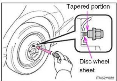
text_image
Tapered portion Disc wheel sheet ITN52Y022Tighten the nuts until the tapered portion comes into loose contact with the disc wheel sheet.
▶ Replacing an aluminum wheel with an aluminum wheel

text_image
Disc wheel Washer ITN52Y023Turn the nut washers until they come into contact with the disc wheel.
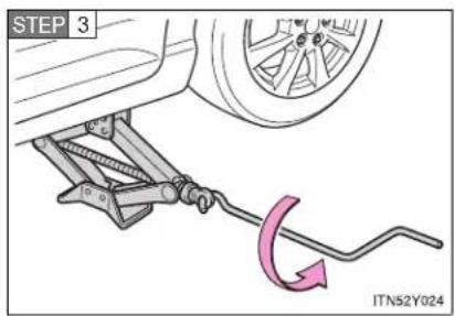
text_image
STEP 3 ITN52Y024Lower the vehicle.

text_image
STEP 4 1 4 2 3 5 ITN52Y025Firmly tighten each nut two or three times in the order shown in the illustration.
Tightening torque:
103 N·m (10.5 kgf·m, 76 ft·lbf)
5-2. Steps to take in an emergency

text_image
STEP 5 ITN52Y026Vehicles with a steel wheel, rein- stall the wheel ornament.
Align the cutout of the wheel ornament with the valve stem as shown.
STEP 6 Stow the flat tire, tire jack and all tools.
The compact spare tire
- The compact spare tire is identified by the label "TEMPORARY USE ONLY" on the tire sidewall. Use the compact spare tire temporarily only in an emergency.
- Make sure to check the tire inflation pressure of the compact spare tire. (→P. 739)
■ If you have a flat front tire on a road covered with snow or ice
Install the compact spare tire on the rear of the vehicle. Perform the following steps and fit tire chains to the front tires.
STEP 1 Replace a rear tire with the compact spare tire.
STEP 2 Replace the flat front tire with the tire removed from the rear of the vehicle.
STEP 3 Fit tire chains to the front tires.
■ Certification for the jack
CE
Manufacturer's Declaration of Conformity
Manufacturer :
ARIKAN KRİKO A.Ş
Organize Sanayi Bölgesi 2.Cd.26110 ESKİŞEHİR / TURKEY
The EU Directives covered by this Declaration
2006 / 42 / EC Machinery Directive
The product covered by this declaration
JACK SUB-ASSY. PANTOGRAPH
model
0.8 ton, 1.1 ton
The basis on which conformity is being declared
The product identified above complies with the requirements of the Machinery Directive
Directive above by meeting following standards
857-ISO 8720
The technical documentation required to demonstrate that the product meets the requirement the Machinery Directive has been compiled by the signatory below and is available for inspection by the relevant enforcement authorities.
A sample of the product has been tested by the manufacturer
Technical File No:2010-TOYOTA JACK-ISO8720-1
The CE mark was first applied in:2010
Done at Shizuoka, Japan
Signature

Date of Issue : 24.08.2010
5-2. Steps to take in an emergency

CAUTION
■ Using the tire jack
Improper use of the tire jack may lead to death or serious injuries due to the vehicle suddenly falling off the jack.
- Do not use the tire jack for any purpose other than replacing tires or installing and removing tire chains.
- Only use the tire jack that comes with this vehicle for replacing a flat tire. Do not use it on other vehicles, and do not use other tire jacks for replacing tires on this vehicle.
● Always check that the tire jack is securely set to the jack point. - Do not put any part of your body under the vehicle supported by a jack.
Do not start or run the engine while your vehicle is supported by the jack. - Do not raise the vehicle while someone is in it.
- When raising the vehicle, do not put an object on or under the jack.
- Do not raise the vehicle to a height greater than that required to replace the tire.
- Use a jack stand if it is necessary to get under the vehicle.
Take particular care when lowering the vehicle to ensure that no one working on or near the vehicle will be injured.

CAUTION
■ Replacing a flat tire
- Observe the following precautions.
Failure to do so may result in serious injury:
- Do not try to remove the wheel ornament by hand. Take due care in handling the ornament to avoid unexpected personal injury.
- Do not attach a heavily damaged wheel ornament, as it may fly off the wheel while the vehicle is moving.
- Failure to follow these precautions could cause the wheel nuts to loosen and the tire to fall off, resulting in death or serious injury.
- Have the wheel nuts tightened with a torque wrench to 103 N·m (10.5 kgf·m, 76 ft·lbf) as soon as possible after changing wheels.
Failure to follow these precautions could cause the nuts to loosen and the wheel may fall off, which could lead to an accident causing death or serious injury. - When installing the wheel nuts, be sure to install the wheel nuts with the tapered ends facing inward. (→P. 559)
When using the standard spare tire (vehicles with a spare tire of different wheel type from the installed tires)
- Replace the standard spare tire with a standard tire as soon as possible.
- Avoid sudden acceleration, deceleration and braking, as well as sharp cornering.
■ When using the compact spare tire
- Remember that your compact spare tire is specifically designed for use with your vehicle. Do not use your compact spare tire on another vehicle.
- Do not use two compact spare tires simultaneously.
- Replace the compact spare tire with a standard tire as soon as possible.
- Avoid sudden acceleration, deceleration and braking, as well as sharp cornering.
5-2. Steps to take in an emergency

CAUTION
■ Speed limit when using the compact spare tire
Do not drive at speeds in excess of 80 km/h (50 mph) when a compact spare tire is installed on the vehicle.
The compact spare tire is not designed for driving at high speeds. Failing to observe this precaution may lead to an accident.
■ When the spare tire is installed
The vehicle speed may not be correctly detected, and the following systems may not operate correctly:
• ABS & brake assist
VSC
TRC
• Navigation system (if equipped)
Toyota parking assist-sensor (if equipped)
• Dynamic radar cruise control (if equipped)
• Cruise control (if equipped)
• PCS (if equipped)
LKA (if equipped)
• AFS (if equipped)

NOTICE
Do not drive the vehicle with a flat tire
Do not continue driving with a flat tire.
Driving even a short distance with a flat tire can damage the tire and the wheel beyond repair.
- Be careful when driving over bumps with the compact spare tire installed on the vehicle
The vehicle becomes lower when driving with the compact spare tire compared to when driving with standard tires. Be careful when driving over uneven road surfaces.
- Driving with tire chains and the compact spare tire
Do not fit tire chains to the compact spare tire.
Tire chains may damage the vehicle body and adversely affect driving performance.
5-2. Steps to take in an emergency
If you have a flat tire (vehicles without a spare tire)
Your vehicle is equipped with an emergency tire puncture repair kit. A puncture caused by a nail or screw passing through the tire tread can be repaired temporarily with the emergency tire puncture repair kit.
■ Before repairing the vehicle
- Stop the vehicle in a safe place on a hard, flat surface.
- Set the parking brake.
- Shift the lever to "P" (Multidrive or automatic transmission) or "N" (manual transmission).
- Stop the engine.
● Turn on the emergency flashers. ( P. 604)
■ Location of the emergency tire puncture repair kit, jack and tools
▶ Sedan

text_image
Emergency tire puncture repair kit Jack* Packing brake release tool Jack handle* Wheel nut wrench Towing eyelet ITI52Y106a*: Use of the jack. (if equipped) (→P. 652)
Wagon
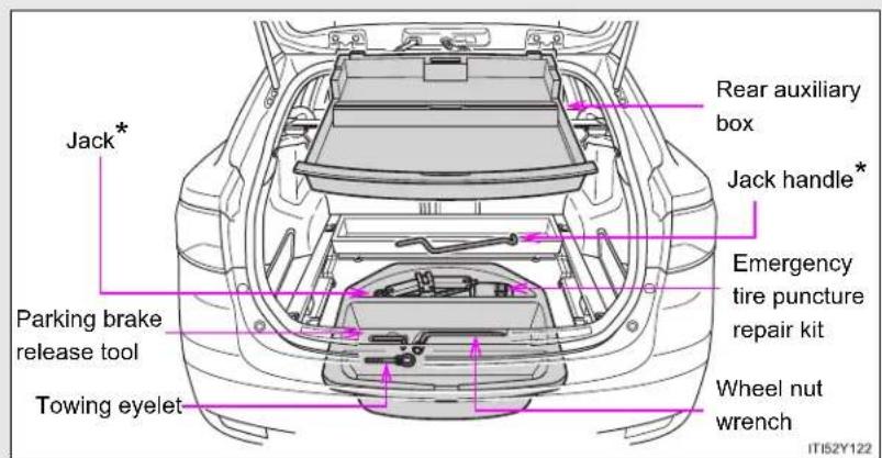
text_image
Jack* Packing brake release tool Towing eyelet Rear auxiliary box Jack handle* Emergency tire puncture repair kit Wheel nut wrench ITIS2Y122*: Use of the jack. (if equipped) (→P. 666)
Contents

text_image
Sealant Injection hose Valve core tool Valve core (spare) Stickers CAUTION selecting air bed in the Tire Stickers Compressor IT152Y125Before putting the sealant into use
Check the degree of the tire damage before making use of the sealant in the emergency tire puncture repair kit.

natural_image
Line drawing of a car wheel rim with visible tire and mounting bracket (no text or symbols)A tire should only to be repaired if the damage is caused by a nail or screw passing through the tire tread. Perform the repair with the nail or screw that has punctured the tire positioned at the bottom, in contact with the ground.
Emergency repair with the sealant in the kit is not possible in the following cases. Contact any authorized Toyota dealer or repairer, or another duly qualified and equipped professional.
● When the wheel is damaged
- When two or more tires have been punctured
- When the tire is damaged due to driving without sufficient tire inflation pressure
- When the tire is visibly disengaged from the wheel
- When the tire has lost tire inflation pressure due to a crack or damage in the tire sidewall
- When the cut or damage to the tread is 4 mm (0.16 in.) or more
Emergency repair method
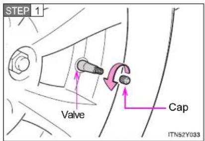
text_image
STEP 1 Valve Cap ITN52Y033Position the nail or screw that has punctured the tire at the bottom, in contact with the ground. Remove the cap from the valve.

text_image
STEP 2 Valve Valve core tool Protruding part ITN52Y034Bring the protruding part of the valve core tool into contact with the valve to discharge air.
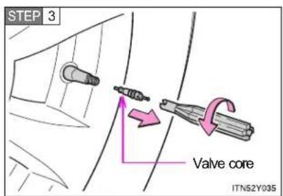
text_image
STEP 3 Valve core ITN52Y035Pull out the valve core by turning it counterclockwise using the valve core tool.
STEP 4 Shake the sealant bottle up and down several times.
STEP 5 Remove the cap of the sealant bottle.
5-2. Steps to take in an emergency
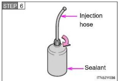
text_image
STEP 6 Injection hose Sealant ITN52Y036Connect the injection hose by screwing onto the sealant. As it is screwed in, the aluminum seal on the bottle will be torn.

text_image
STEP 7 Plug Injection hose ITN52Y037Remove the plug from the injection hose.

text_image
STEP 8 Valve Injection hose ITN52Y038Connect the injection hose to the valve.
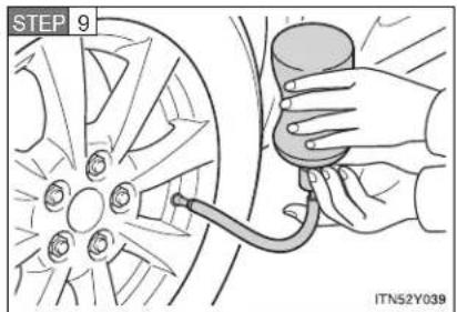
text_image
STEP 9 ITN52Y039Inject the sealant that is in the bottle. Hold and tilt the bottle, then squeeze sealant out of the bottle as shown.
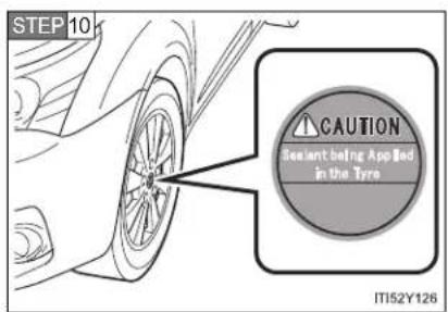
text_image
STEP 10 CAUTION Sealant being Appled in the Tyre IT152Y126Attach the sticker as shown.

text_image
STEP 11 Valve core tool Valve core ITN52Y040Remove the injection hose from the valve and screw the valve core in the valve securely by turning it clockwise with the valve core tool.
5-2. Steps to take in an emergency
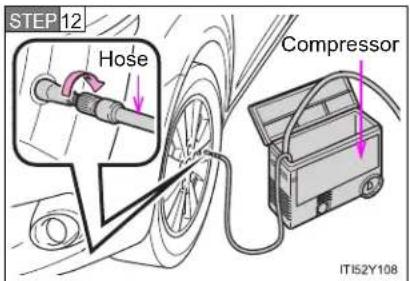
text_image
STEP 12 Hose Compressor ITI52Y108Connect the air compressor hose by threading it on the valve.
STEP 13 Connect the compressor power plug.
Vehicles with smart entry & start system: The "ENGINE START STOP" switch must be in ACCESSORY mode.
Vehicles without smart entry & start system: The engine switch must be in the "ACC" position.
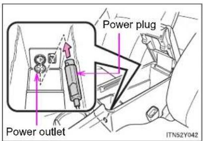
text_image
Power outlet Power plug ITNS2Y042Open the cover and connect the power plug.
STEP 14 Check the specified inflation pressure.
The label is placed as shown in the illustration.
▶ Left-hand drive vehicles
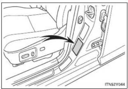
natural_image
Diagram of a car seatbelt switch mechanism showing the grip and seat (no text or symbols present)▶ Right-hand drive vehicles

natural_image
Interior view of a car showing the side panel and seat, with an arrow pointing to a component (no text or symbols visible)
text_image
STEP 15 Switch ITN52Y046Turn the compressor switch "ON" and fill the tire with air until the specified inflation pressure is reached.
5-2. Steps to take in an emergency
STEP 16 Turn the switch "OFF" when the pressure gauge connected to the hose reads the specified pressure.
If the inflation pressure is not attained within 5 minutes, emergency repair is not possible due to severe damage. Contact any authorized Toyota dealer or repairer, or another duly qualified and equipped professional.
STEP 17 After completely filling the tire with air, disconnect the hose from the valve on the tire.
STEP 18 Pull the power plug of the compressor out of the power outlet on the vehicle.
STEP 19 To spread the liquid sealant evenly in the tire, immediately drive for about 5 km (3 miles) or 10 minutes.

text_image
STEP 20 M152Y109After driving about 5 km (3 miles) or 10 minutes, pull your vehicle over in a safe place and reconnect the compressor.
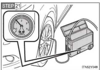
text_image
STEP 21 ITN52Y049Read the inflation pressure on the pressure gauge.

text_image
x100kPa ITN52Y050If the pressure is 130 kPa (1.3 kgf/cm ^2 or bar, 18 psi) or above, fill the tire with air using the compressor until the specified inflation pressure is reached.
If the pressure is less than 130 kPa (1.3 kgf/cm ^2 or bar, 18 psi), the emergency repair that has been performed is not safe for use as damage to the tire is too severe. Do not continue to drive the vehicle. Contact any authorized Toyota dealer or repairer, or another duly qualified and equipped professional.
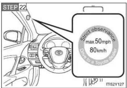
text_image
STEP 22 Strict observance max 50mph 80km/h Down to a Toyota (Rear) IT52Y127Store the kit and then attach the sticker as shown.
Taking precautions to avoid sudden braking and sharp turns, drive carefully at under 80 km/h (50 mph) to the nearest authorized Toyota dealer, tire dealer or repairer, or another duly qualified and equipped professional for tire repair or replacement.
5-2. Steps to take in an emergency
Sealant
- One tire can be repaired using the bottle of sealant stored in the emergency tire puncture repair kit.
- The sealant can be used when the outside temperature is from -30^ (-22^) to 60^ (140^) .
- The sealant has a limited lifespan. The expiry date is marked on the bottle. The sealant should be replaced before the expiry date. Contact any authorized Toyota dealer or repairer, or another duly qualified and equipped professional.
- If the sealant gets on your clothes, it may stain.
- After using the sealant, bring the empty bottle of sealant to any authorized Toyota dealer or repairer, or another duly qualified and equipped professional and purchase a new bottle. Keep the new bottle of sealant in your vehicle.
Compressor
The compressor is a pneumatic filling type for passenger vehicles.
- When the compressor is operating, a loud operating noise will be produced.
This does not indicate a malfunction.
■ The wheel of a tire that has been repaired
If you remove the sealant adhering to the wheel with a rag, you can reuse the wheel. However, in the case of the valve, replace it with a new one.

CAUTION
■ Precaution for children
Keep the emergency tire puncture repair kit out of the reach of children and store it properly.
Sealant precautions
- The sealant in the emergency tire puncture repair kit is not for human consumption.
If the sealant is consumed inadvertently, drink a large quantity of water and get medical attention immediately. - If sealant gets in your eyes or on your skin, thoroughly wash with a large quantity of water. If necessary, get medical attention.
■ When fixing the flat tire
- Stop your vehicle in a safe and flat area.
- If force is used to turn the valve core tool while air remains in the tire, special care should be taken because the valve core could fly out.
- Be careful, as sealant may fly out if you shake the bottle with the hose installed.
- If the hose is not securely installed, sealant may leak out when filling.
- Connect the valve and hose securely with the tire installed on the vehicle
- Be careful handling the compressor, as parts of the compressor get hot during operation. Some parts of the compressor may remain hot after use.
- Driving to spread the liquid sealant evenly
Drive your vehicle with due care. Be especially careful when turning and cornering.
5-2. Steps to take in an emergency

NOTICE
■ Vehicles with a flat tire
Do not continue driving with a flat tire.
Driving even a short distance with a flat tire can damage the tire and the wheel beyond repair.
■ When performing an emergency repair
Perform the emergency repair without removing the nail or screw that has punctured the tread of the tire. If the object that has punctured the tire is removed, the repair using the sealant in the emergency tire puncture repair kit may fail.
When fixing the flat tire
- Do not put the valve core on dirty ground or in the sand. Store it in a clean place.
Do not remove the inside cap of the sealant bottle.
- Turn the valve core tool with your hand when screwing it in. If you use another tool in conjunction with the valve core tool, damage may occur.
- Do not operate the compressor continuously for more than 7 minutes. The motor may overheat and be damaged. Let the compressor cool before using it again.
■ Compressor precautions
The compressor power source should be 12 V DC suitable for vehicle use. Do not connect the compressor to 24 V DC or any other power source.
The compressor is an oil-less type. Do not lubricate with oil.
5-2. Steps to take in an emergency If the engine will not start
If the engine still does not start after following the correct starting procedure ( P. 210, 215) or releasing the steering lock ( P. 213, 217), confirm the following points.
The engine will not start even if you are carrying the correct key
One of the following may be the cause of the problem.
- There may not be sufficient fuel in the vehicle's tank. Gasoline engine: Refuel the vehicle. Diesel engine: (→P. 713)
- The engine may be flooded. (gasoline engine) Try to restart the engine once more following correct starting procedures. (→P. 210, 215) - There may be a malfunction in the engine immobilizer system. (→P. 135)
The starter motor turns over slowly, the personal/interior lights and headlights are dim, or the horn does not sound or sounds at a low volume
One of the following may be the cause of the problem.
● The battery may be discharged. (→P. 705)
● The battery terminal connections may be loose or corroded.
5-2. Steps to take in an emergency
The starter motor does not turn over (vehicles with smart entry & start system)
The engine starting system may be malfunctioning due to an electrical problem such as an open circuit or a blown fuse. However, an interim measure is available to start the engine. (→P. 691)
The starter motor does not turn over, the personal/interior lights and headlights do not turn on, or the horn does not sound
One of the following may be the cause of the problem.
● One or both of the battery terminals may be disconnected.
● The battery may be discharged. (→P. 705)
- There may be a malfunction in the steering lock system. (vehicles with smart entry & start system)
Contact any authorized Toyota dealer or repairer, or another duly qualified and equipped professional, if the problem cannot be repaired, or if repair procedures are unknown.
Emergency start function (Multidrive or automatic transmission vehicles with smart entry & start system)
When the engine does not start, the following steps can be used as an interim measure to start the engine if the "ENGINE START STOP" switch is functioning normally.
STEP 1 Set the parking brake.
STEP 2 Put the shift lever in "P".
STEP 3 Set the "ENGINE START STOP" switch to ACCESSORY mode.
STEP 4 Push and hold the "ENGINE START STOP" switch about 15 seconds while depressing the brake pedal firmly.
Even if the engine can be started using the above steps, the system may be malfunctioning. Have the vehicle checked by any authorized Toyota dealer or repairer, or another duty qualified and equipped professional.
5-2. Steps to take in an emergency
If the shift lever cannot be shifted from "P"
For vehicles with Multidrive or automatic transmission: If the shift lever cannot be shifted with your foot on the brake, there may be a problem with the shift lock system (a system to prevent accidental operation of the shift lever). Have the vehicle inspected by any authorized Toyota dealer or repairer, or another duly qualified and equipped professional, immediately.
The following steps may be used as an emergency measure to ensure that the shift lever can be shifted.
STEP 1 Set the parking brake.
STEP 2 Vehicles with smart entry & start system: Turn the "ENGINE START STOP" switch to ACCESSORY mode.
Vehicles without smart entry & start system: Turn the engine switch to the "ACC" position.
STEP 3 Depress the brake pedal.
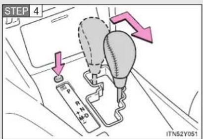
text_image
STEP 4 P P+N H+O ITN52Y051Press the "SHIFT LOCK" button.
The shift lever can be shifted while the button is pressed.
5-2. Steps to take in an emergency
If the parking brake cannot be released
In the event that the battery is discharged or switch operation does not release the parking brake, the parking brake can be released manually using the procedure below. This procedure should be performed only if necessary, such as in an emergency.
If the switch cannot be operated even when the battery is normal, the parking brake system may be malfunctioning. Have the vehicle inspected by any authorized Toyota dealer or repairer, or another duly qualified and equipped professional immediately.
Before releasing the parking brake manually
- Vehicles with a Multidrive or automatic transmission: Shift the shift lever to "P".
- Vehicles with a manual transmission: Shift the shift lever to "1" or "R".
- Vehicles with smart entry & start system: Turn the "ENGINE START STOP" switch OFF.
- Vehicles without smart entry & start system: Turn the engine switch to the "LOCK" position.
- Check that the parking brake indicator is off.
- Chock the tires.
- Stop the vehicle on a hard, flat surface.
Releasing the parking brake manually (sedan)
STEP 1 Lift the luggage mat. ( P. 506)
STEP 2 Take out the parking brake release tool from the trunk.
(→P. 648, 676)
5-2. Steps to take in an emergency
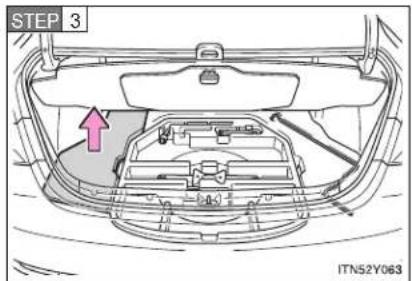
text_image
STEP 3 ITN52Y063Turn over the left side floor mat in the trunk.

text_image
STEP 4 ITN52Y064Remove or break the seal covering the releasing hole.
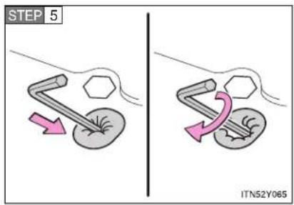
text_image
STEP 5 ITN52Y065Push the parking brake release tool in as far as it will go, making sure that it does not move when your hand is released, and turn it clockwise until the clutch sound is heard. (approx. 600 revolutions, approx. 20 minutes)
It spins free if rotate the releasing tool in counterclockwise direction.
After releasing the parking brake, make sure to remove the release tool and place it in the tool tray.
Releasing the parking brake manually (wagon)
STEP 1 Take out the parking brake release tool from the luggage compartment. (→P. 662, 677)
STEP 2 Lift the left side deck board. (→P. 509)

text_image
STEP 3 ITN52Y066Turn over the luggage box cap.
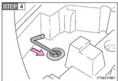
text_image
STEP 4 ITN52Y067Remove or break the seal covering the releasing hole.
5-2. Steps to take in an emergency
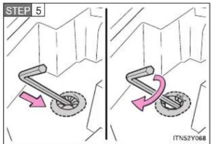
text_image
STEP 5 ITN52Y068Push the parking brake release tool in as far as it will go, making sure that it does not move when your hand is released, and turn it clockwise until the clutch sound is heard. (approx. 600 revolutions, approx. 20 minutes)
It spins free if rotate the releasing tool in counterclockwise direction.
After releasing the parking brake, make sure to remove the release tool and place it in the tool tray.
■ When the seal is damaged
The seal needs to replace by any authorized Toyota dealer or repairer, or another duly qualified and equipped professional.
If the trunk/luggage compartment has flooded with water when the seal has been broken or is missing (for example, if the vehicle has been left outside in the rain with the trunk lid open or removed), the parking brake system will need to be replaced.
■ Manual operation of the parking brake
The parking brake cannot be set manually.

CAUTION
■ When releasing the parking brake manually
▶ Vehicles with smart entry & start system
- Shift the shift lever to "P" (Multidrive or automatic transmission) or "1" or "R" (manual transmission), turn the "ENGINE START STOP" switch OFF and chock the tires.
Failure to do so may cause the vehicle to move, resulting in an accident. - Turn the "ENGINE START STOP" switch OFF and check that the parking brake indicator is off.
Failure to do so may cause the system to operate and turn the parking brake release tool that is inserted, resulting in an injury.
▶ Vehicles without smart entry & start system
- Shift the shift lever to "P" (Multidrive or automatic transmission) or "1" or "R" (manual transmission), turn the engine switch to "LOCK" position and chock the tires.
Failure to do so may cause the vehicle to move, resulting in an accident.
- Turn the engine switch to "LOCK" position and check that the parking brake indicator is off.
Failure to do so may cause the system to operate and turn the parking brake release tool that is inserted, resulting in an injury.
5-2. Steps to take in an emergency

NOTICE
■ When releasing the parking brake manually
- Be sure to turn the tool as far as it will go.
Stopping midway will cause switch operation to cancel and will cause the parking brake system to fail.
• Use designated releasing tool only.
Using commercially available tool may damage the releasing hole and unable to remove the hole.
5-2. Steps to take in an emergency If you lose your keys
New genuine Toyota keys can be made by any authorized Toyota dealer or repairer, or another duly qualified and equipped professional. For vehicles with smart entry & start system, bring the other keys and the key number stamped on your key number plate. For vehicles without smart entry & start system, bring a master key and the key number stamped on the key number plate.
5-2. Steps to take in an emergency
If you cannot operate the trunk opener (sedan)
If the trunk opener does not operate, there may be a problem with the trunk opener system. Have the vehicle inspected by any authorized Toyota dealer or repairer, or another duly qualified and equipped professional immediately.
The following steps may be used as an emergency measure to ensure that the trunk can be opened from the inside.
STEP 1 Folding down the right hand seatback. (→P. 101)

text_image
STEP 2 ITN52Y052bPull the emergency release lever.
5-2. Steps to take in an emergency
If you cannot operate the back door opener (wagon)
If the back door opener does not operate, there may be a problem with the back door opener system. Have the vehicle inspected by any authorized Toyota dealer or repairer, or another duly qualified and equipped professional immediately.
The following steps may be used as an emergency measure to ensure that the back door can be opened from the inside.
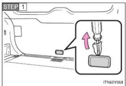
text_image
STEP 1 ITN52Y053Remove the cover on the back door trim.
Use a cloth to prevent scratches.
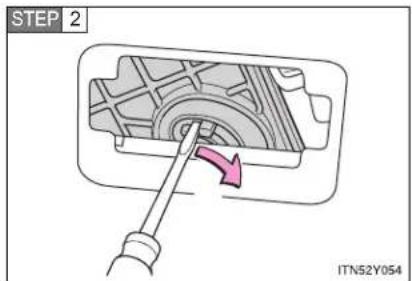
text_image
STEP 2 ITN52Y054Push the lever with the back door motor, and open the back door.
5-2. Steps to take in an emergency
If the electronic key does not operate properly
For vehicles with smart entry & start system: If communication between the electronic key and vehicle is interrupted (→P. 44) or the electronic key cannot be used because the battery is depleted, the smart entry & start system and wireless remote control cannot be used. In such cases, the doors can be opened or the engine can be started by following the procedure below.
Locking and unlocking the doors and key linked functions

text_image
1 2 ITN52Y0551 Locks all doors
2 Unlocks all doors
An alarm will sound if the alarm is set. (→P. 146)
Changing "ENGINE START STOP" switch modes and starting the engine
STEP 1 Vehicles with a Multidrive or automatic transmission: Shift the shift lever to "P" and apply the brakes.
Vehicles with a manual transmission: Shift the shift lever to "N" and depress the clutch pedal.
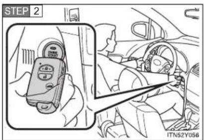
text_image
STEP 2 ITN52Y056Touch the Toyota emblem side of the electronic key to the "ENGINE START STOP" switch.
An alarm will sound to indicate that the start function cannot detect the electronic key that is touched to the "ENGINE START STOP" switch if any of the doors is opened while the key is touched to the switch.
5-2. Steps to take in an emergency
STEP 3 To change "ENGINE START STOP" switch modes: Within 10 seconds of the buzzer sounding, release the brake pedal (Multidrive or automatic transmission) or clutch pedal (manual transmission) and press the "ENGINE START STOP" switch. Modes can be changed each time the switch is pressed. (→P. 212)
To start the engine: Press the "ENGINE START STOP" switch within 10 seconds after the buzzer sounds, keeping the brake pedal (Multidrive or automatic transmission) or clutch pedal (manual transmission) depressed.
In the event that the "ENGINE START STOP" switch still cannot be operated, contact any authorized Toyota dealer or repairer, or another duly qualified and equipped professional.
■ Stopping the engine
Shift the shift lever to "P" (Multidrive or automatic transmission) or "N" (manual transmission) and press the "ENGINE START STOP" switch as you normally do when stopping the engine.
■ Replacing the key battery
As this procedure is a temporary measure, it is recommended that the electronic key battery be replaced immediately when the battery depletes. (→P. 564)
Alarm
Using the mechanical key to lock the doors will not set the alarm system. If a door is unlocked using the mechanical key when the alarm system is set, the alarm may be triggered. (→P. 146)
5-2. Steps to take in an emergency If the battery is discharged
The following procedures may be used to start the engine if the vehicle's battery is discharged.
You can also call any authorized Toyota dealer or repairer, or another duly qualified and equipped professional.
If you have a set of jumper (or booster) cables and a second vehicle with a 12-volt battery, you can jump start your Toyota following the steps below.
STEP 1 Connect the jumper cables.
▶ Gasoline engine
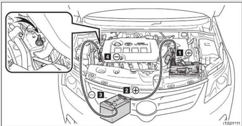
text_image
Diagram of car engine compartment with labeled components and wiring, showing engine body, battery, and wiring connections.5-2. Steps to take in an emergency
▶ Diesel engine
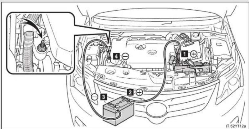
text_image
Diagram of car engine compartment with labeled components and wiring, showing electrical connections and battery connection1 Positive (+) battery terminal on your vehicle
2 Positive (+) battery terminal on the second vehicle
3 Negative (-) battery terminal on the second vehicle
4 Connect the jumper cable to ground on your vehicle as shown in the illustration.
STEP 2 Start the engine of the second vehicle. Increase the engine speed slightly and maintain at that level for approximately 5 minutes to recharge the battery of your vehicle.
STEP 3 Vehicles with smart entry & start system: Open and close any of the doors with the "ENGINE START STOP" switch OFF.
STEP 4 Vehicles with smart entry & start system: Maintain the engine speed of the second vehicle and turn the "ENGINE START STOP" switch to IGNITION ON mode, then start the vehicle's engine.
Vehicles without smart entry & start system: Maintain the engine speed of the second vehicle and turn the engine switch to the "ON" position, then start the vehicle's engine.
STEP 5 Once the vehicle's engine has started, remove the jumper cables in the exact reverse order in which they were connected.
Once the engine starts, have the vehicle checked at any authorized Toyota dealer or repairer, or another duly qualified and equipped professional, as soon as possible.
5-2. Steps to take in an emergency
■ Starting the engine when the battery is discharged (vehicles with a Multidrive or automatic transmission)
The engine cannot be started by push-starting.
■ Avoiding a discharged battery
- Turn off the headlights and the audio system while the engine is turned off.
- Turn off any unnecessary electrical components when the vehicle is running at a low speed for an extended period, such as in heavy traffic, etc.
- Charging the battery
The electricity stored in the battery will discharge gradually even when the vehicle is not in use, due to natural discharge and the draining effects of certain electrical appliances. If the vehicle is left for a long time, the battery may discharge, and the engine may be unable to start. (The battery recharges automatically during driving.)

CAUTION
■ Avoiding battery fires or explosions
Observe the following precautions to prevent accidentally igniting the flammable gas that may be emitted from the battery.
Make sure the jumper cable is connected to the correct terminal and that it is not unintentionally in contact with any part other than the intended terminal.
- Do not allow the jumper cables to come into contact with the "+" and "-" terminals.
- Do not allow open flame or use matches, cigarette lighters or smoke near the battery.

CAUTION
Battery precautions
The battery contains poisonous and corrosive acidic electrolyte, while related parts contain lead and lead compounds. Observe the following precautions when handling the battery.
- When working with the battery, always wear safety glasses and take care not to allow any battery fluids (acid) to come into contact with skin, clothing or the vehicle body.
Do not lean over the battery. - In the event that battery fluid comes into contact with the skin or eyes, immediately wash the affected area with water and seek medical attention. Place a wet sponge or cloth over the affected area until medical attention can be received.
● Always wash your hands after handling the battery support, terminals, and other battery-related parts. - Do not allow children near the battery.

NOTICE
■ To prevent damaging the vehicle (vehicles with a manual transmission)
Do not pull- or push-start the vehicle, because the catalytic converter may overheat and become a fire hazard.
■ When handling jumper cables
Be careful that the jumper cables do not become tangled in the cooling fan or any of the belts when connecting or disconnecting them.
5-2. Steps to take in an emergency
If your vehicle overheats
If your engine overheats:
STEP 1 Stop the vehicle in a safe place and turn off the air conditioning system.
STEP 2 Check to see if steam is coming out from under the hood.
If you see steam:
Stop the engine. Carefully lift the hood after the steam subsides and then restart the engine.
If you do not see steam:
Leave the engine running and carefully lift the hood.
STEP 3 Check to see if the cooling fan is operating.
If the fan is operating:
Wait until the engine coolant temperature gauge begins to fall and then stop the engine.
If the fan is not operating:
Stop the engine and call any authorized Toyota dealer or repairer, or another duly qualified and equipped professional.

natural_image
Line drawing of a car engine bay with visible components and no text or symbolsAfter the engine has cooled down sufficiently, check the engine coolant level and inspect the radiator core (radiator) for any leaks.
If the engine compartment cover needs to be removed: →P. 537
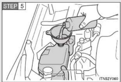
text_image
STEP 5 ITN52Y060Add engine coolant if necessary.
Water can be used in an emergency if engine coolant is unavailable. (→P. 733)
Have the vehicle checked at the nearest authorized Toyota dealer or repairer, or another duly qualified and equipped professional, as soon as possible.
Overheating
If you observe the following, your vehicle may be overheating.
- The engine coolant temperature gauge enters the red zone or a loss of power is experienced.
- Steam is coming from under the hood.

CAUTION
■ To prevent an accident or injury when inspecting under the hood of your vehicle
- If steam is seen coming from under the hood, do not open the hood until the steam has subsided. The engine compartment may be very hot, causing serious injury such as burns.
- Keep hands and clothing away from the fan and other belts while the engine is running.
- Do not loosen the coolant reservoir cap while the engine and radiator are hot.
Serious injury, such as burns, may result from hot coolant and steam released under pressure.

NOTICE

When adding engine coolant
Wait until the engine has cooled down before adding engine coolant. When adding coolant, do so slowly. Adding cool coolant to a hot engine too quickly can cause damage to the engine.
5-2. Steps to take in an emergency
If you run out of fuel and the engine stalls (diesel engine)
If you run out of fuel and the engine dies:
STEP 1 Refuel your vehicle.

text_image
STEP 2 IT152Y114aOperate the priming pump until you feel more resistance to bleed the fuel system.
STEP 3 Start the engine. ( P. 210, 215)
If the engine does not start after the above steps have been performed, wait for 10 seconds and try step 2 and 3 again. If the engine still does not start, contact any authorized Toyota dealer or repairer, or another duly qualified and equipped professional.
After starting the engine, depress the accelerator pedal lightly until the engine runs smoothly.
NOTICE
■ When restarting the engine
- Do not crank the engine before refueling and operating the priming pump. This may damage the engine and fuel system.
- Vehicles without smart entry & start system: Do not crank for more than 30 seconds at a time. This may overheat the starter and wiring system.
5-2. Steps to take in an emergency If the vehicle becomes stuck
Carry out the following procedures if the tires spin or the vehicle becomes stuck in mud, dirt, or snow.
STEP 1 Stop the engine. Set the parking brake and put the shift lever in "P" (Multidrive or automatic transmission) or "N" (manual transmission).
STEP 2 Remove the mud, snow, or sand from around the stuck tire.
STEP 3 Place wood, stones or some other material to help provide traction under the tires.
STEP 4 Restart the engine.
STEP 5 Shift the shift lever to the "D" or "R" position (Multidrive or automatic transmission) or "1" or "R" position (manual transmission) and carefully apply the accelerator to free the vehicle.
Turn off the TRC and/or VSC systems if it is difficult to get out because of TRC and/or VSC operation. ( P. 328)

CAUTION
■ When attempting to free a stuck vehicle
If you choose to rock the vehicle back and forth to free it, make sure the surrounding area is clear, to avoid striking other vehicles, objects or persons. The vehicle may also lunge forward or lunge back suddenly as it becomes free. Use extreme caution.
■ When shifting the shift lever
Vehicles with a Multidrive or automatic transmission: Be careful not to shift the shift lever with the accelerator pedal depressed. This may lead to unexpected rapid acceleration of the vehicle that may cause an accident and result in death or serious injury.

NOTICE
To avoid damaging the transmission and other components
- Avoid spinning the wheels and do not rev the engine.
- If the vehicle remains stuck after trying these procedures, the vehicle may require towing to be freed.
5-2. Steps to take in an emergency
If your vehicle has to be stopped in an emergency
Only in an emergency, such as if it becomes impossible to stop the vehicle in the normal way, stop the vehicle using the following procedure:
STEP 1 Steadily step on the brake pedal with both feet and firmly depress it.
Do not pump the brake pedal repeatedly as this will increase the effort required to slow the vehicle.
STEP 2 Shift the shift lever to "N".
▶ If the shift lever is shifted to "N"
STEP 3 After slowing down, stop the vehicle in a safe place by the road.
STEP 4 Stop the engine.
▶ If the shift lever cannot be shifted to "N"
STEP 3 Keep depressing the brake pedal with both feet to reduce vehicle speed as much as possible.
STEP 4
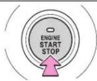
Press and hold for 3 seconds or more, or press briefly 3 times or more
CTY52AD216
Vehicles with a smart entry & start system: To stop the engine, press and hold the "ENGINE START STOP" switch for 3 consecutive seconds or more, or press it briefly 3 times or more in succession.

text_image
STEP 4 PUSH ACC OR 100 CTN52AF211Vehicles without smart entry & start system: Stop the engine by turning the engine switch to the "ACC" position.
STEP 5 Stop the vehicle in a safe place by the road.

CAUTION
If the engine has to be turned off while driving
● Power assist for the brakes and steering wheel will be lost, making the brake pedal harder to depress and the steering wheel heavier to turn. Decelerate as much as possible before turning off the engine.
- Vehicles without smart entry & start system: Never attempt to remove the key, as doing so will lock the steering wheel.
5-2. Steps to take in an emergency
Vehicle specifications
6
6-1. Specifications
Maintenance data
(fuel, oil level, etc.)...... 720
Fuel information 745
6-2. Customization
Customizable
features...... 749
6-3. Initialization
Items to initialize 754
6-1. Specifications
Maintenance data (fuel, oil level, etc.)
Dimensions and weights
| Overall length | Sedan 4710 mm (185.4 in.) | |
| Wagon 4780 mm (188.2 in.) | ||
| Overall width 1810 mm (71.2 in.) | ||
| Overall height*1 | 1480 mm (58.2 in.) | |
| Wheelbase 2700 mm (106.3 in.) | ||
| Tread | Front | 1560 mm (61.4 in.)*21550 mm (61.0 in.)*3 |
| Rear | 1550 mm (61.0 in.)*21540 mm (60.6 in.)*3 | |
| Gross vehicle mass | 1ZR-FAE engine 1950 kg (4298.9 lb.) | |
| 2ZR-FAE engine | 2020 kg (4453.3 lb.)*42000 kg (4409.2 lb.)*5 | |
| 3ZR-FAE engine | 2050 kg (4519.4 lb.)*42020 kg (4453.3 lb.)*5 | |
| 1AD-FTV engine | 2100 kg (4629.7 lb.)2130 kg (4695.8 lb.)*6 | |
| 2AD-FTV and 2AD-FHV engines | 2140 kg (4717.8 lb.) | |
| Maximum permissible axle capacity | Front | 1215 kg (2678.6 lb.)*71250 kg (2755.7 lb.)*8 |
| Rear | 1135 kg (2502.2 lb.)*71215 kg (2678.6 lb.)*8 | |
| Drawbar load 75 kg (165.3 lb.) | ||
| Towing capacity | With brake | ► 1ZR-FAE engine1400 kg (3086.4 lb.)► 2ZR-FAE engine1600 kg (3527.3 lb.)* ^4 1500 kg (3306.9 lb.)* ^5 ► 3ZR-FAE engine1800 kg (3968.3 lb.)* ^4 1500 kg (3306.9 lb.)* ^5 ► 1AD-FTV engine1600 kg (3527.3 lb.)► 2AD-FTV engine1800 kg (3968.3 lb.)► 2AD-FHV engine1800 kg (3968.3 lb.)* ^5 1600 kg (3527.3 lb.)* ^9 |
| Without brake 500 kg (1 | 102.3 lb.) | |
*1: Unladen vehicles
^2 : 205/60R16 tires
*3: 215/55R17 and 225/45R18 tires
*4: Vehicles with a Multidrive
*5: Vehicles with a manual transmission
^6 : ADT270L-AWFEYW and ADT270R-AWFEYW models
The model code is indicated on the manufacturer's label. ( P. 722)
*7: Vehicle category M1 models
*8: Vehicle category N1 models
*9: Vehicles with an automatic transmission
To distinguish the vehicle category, ask any authorized Toyota dealer or repairer, or another duly qualified and equipped professional.
6-1. Specifications
Vehicle identification
■ Vehicle identification number
The vehicle identification number (VIN) is the legal identifier for your vehicle. This is the primary identification number for your Toyota. It is used in registering the ownership of your vehicle.

text_image
FRAME No. ITN61Y001Left-hand drive vehicles: This number is stamped under the front passenger seat.
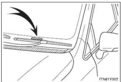
natural_image
Mechanical diagram showing a lever mechanism with an arrow indicating motion (no text or symbols present)Right-hand drive vehicles: This number is stamped on the top left of the instrument panel.

natural_image
Diagram of a car door seat and side panel showing a black arrow pointing to the door panel (no text or symbols present)This number is also on the manufacturer's label.
Engine number
The engine number is stamped on the engine block as shown.
▶ Gasoline engine
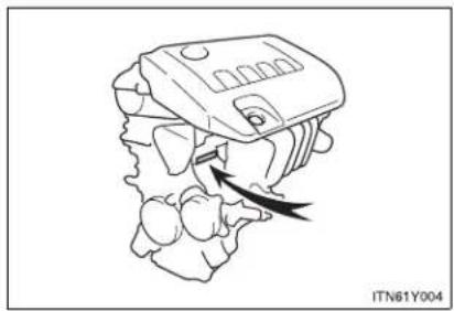
natural_image
Line drawing of a mechanical component with an arrow indicating direction, no text or symbols present▶ Diesel engine
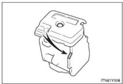
natural_image
Technical line drawing of a mechanical component with an arrow indicating direction (no text or symbols)Engine
▶ Gasoline engine
| Model 1ZR-FAE, 2ZR-FAE | E, 3ZR-FAE |
| Type 4-cylinder in line, 4-cycle, gasoline | |
| Bore and stroke | ► 1ZR-FAE engine80.5 × 78.5 mm (3.17 × 3.09 in.)► 2ZR-FAE engine80.5 × 88.3 mm (3.17 × 3.48 in.)► 3ZR-FAE engine80.5 × 97.6 mm (3.17 × 3.84 in.) |
| Displacement | ► 1ZR-FAE engine1598 cm3(97.5 cu.in.)► 2ZR-FAE engine1798 cm3(109.7 cu.in.)► 3ZR-FAE engine1987 cm3(121.2 cu.in.) |
| Valve clearance (engine cold) | Automatic adjustment |
| Drive belt tension | 7.6 — 10.0 mm (0.30 — 0.39 in.)* *: Drive belt deflection with 98 N (10 kgf, 22 lbf) thumb force (used belt) *: Drive belt deflection with 98 N (10 kgf, 22 lbf) thumb force (used belt) |
▶ Diesel engine
| Model 1AD-FTV, 2AD-FTV, 2AD-FHV | |
| Type 4-cylinder in line, 4-cycle, diesel | |
| Bore and stroke | ▶ 1AD-FTV engine86.0 x 86.0 mm (3.39 × 3.39 in.)▶ 2AD-FTV and 2AD-FHV engines86.0 x 96.0 mm (3.39 × 3.78 in.) |
| Displacement | ▶ 1AD-FTV engine1998 cm ^3 (121.9 cu. in.)▶ 2AD-FTV and 2AD-FHV engines2231 cm ^3 (136.1 cu.in.) |
| Valve clearance (engine cold) | Automatic adjustment |
| Drive belt tension Automatic adjustment | |
Fuel
▶ Gasoline engine
| Fuel type | EU area:Unleaded gasoline conforming to European standard EN228 onlyExcept EU area:Unleaded gasoline only |
| Research octane number | 95 or higher |
| Fuel tank capacity (reference) | 60 L (15.9 gal., 13.2 Imp.gal.) |
6-1. Specifications
▶ Diesel engine
| Fuel type | 1AD-FTV engine | ► Vehicles with DPF catalytic converterEU area:Diesel fuel conforming to European standard EN590Except EU area:Diesel fuel that contains 50 ppm or less of sulfur► Vehicles without DPF catalytic converterEU area:Diesel fuel conforming to European standard EN590Except EU area:Diesel fuel that contains 500 ppm or less of sulfur |
| 2AD-FTV and 2AD-FHV engines | EU area:Diesel fuel conforming to European standard EN590Except EU area:Diesel fuel that contains 50 ppm or less of sulfur | |
| Cetane number 48 or higher | ||
| Fuel tank capacity (reference) | 60 L (15.9 gal., 13.2 Imp.gal.) | |
Lubrication system
| Oil capacity(Drain and refill — reference*)▶ Gasoline engine▶ Diesel engine | With filter: 4.2 L (4.4 qt., 3.7 Imp.qt.)Without filter: 3.9 L (4.1 qt., 3.4 Imp.qt.)▶ 1AD-FTV engine (vehicles with DPF catalytic converter)With filter: 5.9 L (6.2 qt., 5.2 Imp.qt.)Without filter: 5.5 L (5.8 qt., 4.8 Imp.qt.)▶ 1AD-FTV engine (vehicles without DPF catalytic converter)With filter: 6.3 L (6.7 qt., 5.5 Imp.qt.)Without filter: 5.9 L (6.2 qt., 5.2 Imp.qt.)▶ 2AD-FTV and 2AD-FHV enginesWith filter: 5.9 L (6.2 qt., 5.2 Imp.qt.)Without filter: 5.5 L (5.8 qt., 4.8 Imp.qt.) |
*: The engine oil capacity is a reference quantity to be used when changing the engine oil. Warm up and turn off the engine, wait more than 5 minutes, and check the oil level on the dipstick.
Engine oil selection
"Toyota Genuine Motor Oil" is used in your Toyota vehicle. Toyota recommends the use of approved "Toyota Genuine Motor Oil". Another motor oil of matching quality can also be used.
▶ Gasoline engine
Oil grade:
0W-20, 5W-20, 5W-30 and 10W-30:
API grade SL "Energy-Conserving", SM "Energy-Conserving", SN "Resource-Conserving" or ILSAC multigrade engine oil
15W-40 and 20W-50:
API grade SL, SM or SN multigrade engine oil
Recommended viscosity (SAE):

bar
| Temperature Range | Value | | :--- | :--- | | 0W-20 Preferred | 18 | | 5W-20 | 16 | | 5W-30 | 14 | | 10W-30 | 12 | | 15W-40 | 10 | | 20W-50 | 8 | | 27 | 6 | | 38 | 4 | | 100 | 2 | | -7 | 0 | | -29 | -2 | | -18 | -4 | | -20 | -6 | | 0 | -8 | | 20 | -10 | | 40 | -12 | | 60 | -14 | | 80 | -16 | | 100 | -18 |SAE 0W-20 is filled into your Toyota vehicle at manufacturing, and the best choice for good fuel economy and good starting in cold weather.
If SAE 0W-20 oil is not available, SAE 5W-30 oil may be used. However, it should be replaced with SAE 0W-20 at the next oil change.
If you use SAE 10W-30 or a higher viscosity engine oil in extremely low temperatures, the engine may become difficult to start, so SAE 5W-30 or lower viscosity engine oil is recommended.
Oil viscosity (0W-20 is explained here as an example):
- The 0W in 0W-20 indicates the characteristic of the oil which allows cold startability. Oils with a lower value before the W allow for easier starting of the engine in cold weather.
- The 20 in 0W-20 indicates the viscosity characteristic of the oil when the oil is at high temperature. An oil with a higher viscosity (one with a higher value) may be better suited if the vehicle is operated at high speeds, or under extreme load conditions.
How to read oil container labels:
Either or both API registered marks are added to some oil containers to help you select the oil you should use.
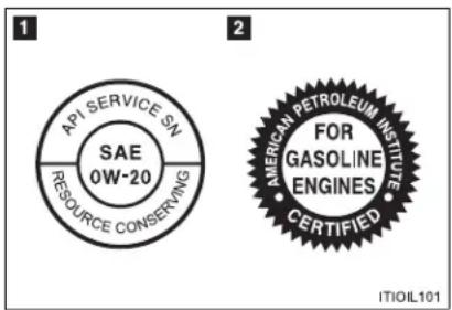
text_image
API SERVICE SN SAE 0W-20 RESOURCE CONSERVING 2 AMERICAN PETROLEUM INSTITUTE FOR GASOLINE ENGINES CERTIFIED ITIOIL1011 API Service Symbol
Top portion: The oil quality designation by API (American Petroleum Institute) (SN)
Center portion: The SAE viscosity grade (SAE 0W-20)
Lower portion: "Resource-Conserving" means that the oil has fuel saving and environmental protection.
2 ILSAC Certification Mark
The ILSAC (International Lubricant Standardization and Approval Committee) Certification Mark is displayed on the front of the container.
6-1. Specifications
▶ 1AD-FTV engine without DPF catalytic converter
● Diesel fuel that contains between 50 ppm and 500 ppm of sulfur
Oil grade:
ACEA B1, API CF-4 or CF
(You may also use API CE or CD.)
Recommended viscosity (SAE):
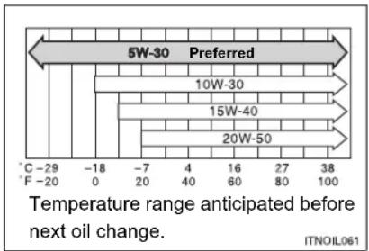
bar
| Temperature Range | Oil Type | | :--- | :--- | | -29 to -20 | C | | -20 to -18 | F | | -7 to -4 | 0 | | -7 to 4 | 20 | | -7 to 4 | 40 | | -7 to 4 | 60 | | -7 to 4 | 80 | | -7 to 4 | 100 | | 16 to 27 | 5W-30 Preferred | | 16 to 27 | 10W-30 Preferred | | 16 to 27 | 15W-40 Preferred | | 16 to 27 | 20W-50 Preferred | | 38 to 100 | ITNOIL061SAE 5W-30 is filled into your Toyota vehicle at manufacturing, and the best choice for good fuel economy and good starting in cold weather.
If you use SAE 10W-30 or a higher viscosity engine oil in extremely low temperatures, the engine may become difficult to start, so SAE 5W-30 engine oil is recommended.
Oil viscosity (5W-30 is explained here as an example):
- The 5W in 5W-30 indicates the characteristic of the oil which allows cold startability. Oils with a lower value before the W allow for easier starting of the engine in cold weather.
- The 30 in 5W-30 indicates the viscosity characteristic of the oil when the oil is at high temperature. An oil with a higher viscosity (one with a higher value) may be better suited if the vehicle operated at high speeds, or under extreme load conditions.
● Diesel fuel that contains 50 ppm or less of sulfur
Oil grade:
ACEA C2, B1, API CF-4 or CF
(You may also use API CE or CD.)
Recommended viscosity (SAE):
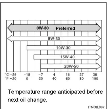
bar
| Temperature Range | Value | | :--- | :--- | | 0W-30 Preferred | 0 | | 5W-30 | 5 | | 10W-30 | 10 | | 15W-40 | 15 | | 20W-50 | 20 | | 38 | 38 | T: Temperature range anticipated before next oil change. ITNOIL067SAE 0W-30 is filled into your Toyota vehicle at manufacturing, and the best choice for good fuel economy and good starting in cold weather.
If you use SAE 10W-30 or a higher viscosity engine oil in extremely low temperatures, the engine may become difficult to start, so SAE 5W-30 or 0W-30 engine oil is recommended.
Oil viscosity (0W-30 is explained here as an example):
- The 0W in 0W-30 indicates the characteristic of the oil which allows cold startability. Oils with a lower value before the W allow for easier starting of the engine in cold weather.
- The 30 in 0W-30 indicates the viscosity characteristic of the oil when the oil is at high temperature. An oil with a higher viscosity (one with a higher value) may be better suited if the vehicle is operated at high speeds, or under extreme load conditions.
6-1. Specifications
▶ 1AD-FTV engine with DPF catalytic converter, 2AD-FTV and 2AD-FHV engines
Oil grade: ACEA C2

NOTICE
Using engine oil other than ACEA C2 may damage the catalytic converter.
Recommended viscosity (SAE):
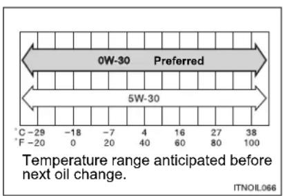
text_image
0W-30 Preferred 5W-30 Temperature range anticipated before next oil change. C -29 -18 -7 4 16 27 38 F -20 0 20 40 60 80 100 ITNOIL066SAE 0W-30 is filled into your Toyota vehicle at manufacturing, and the best choice for good fuel economy and good starting in cold weather.
Oil viscosity (0W-30 is explained here as an example):
- The 0W in 0W-30 indicates the characteristic of the oil which allows cold startability. Oils with a lower value before the W allow for easier starting of the engine in cold weather.
- The 30 in 0W-30 indicates the viscosity characteristic of the oil when the oil is at high temperature. An oil with a higher viscosity (one with a higher value) may be better suited if the vehicle is operated at high speeds, or under extreme load conditions.
Cooling system
| Capacity (reference) | Gasoline engine | ► 1ZR-FAE engine6.3 L (6.7 qt., 5.5 Imp.qt.)► 2ZR-FAE and 3ZR-FAE enginesMultidrive: 6.2 L (6.6 qt., 5.4 Imp.qt.)Manual transmission: 6.3 L (6.7 qt., 5.5 Imp.qt.) |
| Diesel engine | ► With power heater7.8 L (8.2 qt., 6.9 Imp.qt.)► Without power heater7.4 L (7.8 qt., 6.5 Imp.qt.) | |
| Coolant type | Use either of the following."Toyota Super Long Life Coolant"Similar high-quality ethylene glycol-based non-silicate, non-amine, non-nitrite, and non-borate coolant with long-life hybrid organic acid technologyDo not use plain water alone. | |
6-1. Specifications
Ignition system (gasoline engine)
| Spark plugMake DENSO SC20HR11Gap 1.1 mm (0.043 in.) |

NOTICE
- Iridium-tipped spark plugs
Use only iridium-tipped spark plugs. Do not adjust gap when tuning engine.
Electrical system
| BatteryOpen voltage at 20°C (68°F): | 12.6 — 12.8 V Fully charged12.2 — 12.4 V Half charged11.8— 12.0 V Discharged(Voltage is checked 20 minutes after the engine and all the lights are turned off.) |
| Charging rates 5 A max. |
Multidrive
| Fluid capacity (reference) | 2ZR-FAE engine 7.7 | L (8.1 qt., 6.7 Imp.qt.) |
| 3ZR-FAE engine 9.1 | L (9.6 qt., 8.0 Imp.qt.) | |
| Fluid type Toyota Genuine CVTF TC | ||
The fluid capacity is the quantity of reference. If replacement is necessary, contact any authorized Toyota dealer or repairer, or another duly qualified and equipped professional.

NOTICE
■ Multidrive fluid type
Using transmission fluid other than “Toyota Genuine CVTF TC” may cause deterioration in shift quality, locking up of your transmission accompanied by vibration, and ultimately damage the transmission of your vehicle.
Automatic transmission
| Fluid capacity (reference) 6.5 L (6.8 qt., 5.5 Imp.qt.) | |
| Fluid type Toyota Genuine ATF WS | |
The fluid capacity is the quantity of reference. If replacement is necessary, contact any authorized Toyota dealer or repairer, or another duly qualified and equipped professional.

NOTICE
■ Automatic transmission fluid type
Using transmission fluid other than “Toyota Genuine ATF WS” may cause deterioration in shift quality, locking up of your transmission accompanied by vibration, and ultimately damage the transmission of your vehicle.
Manual transmission
| Gear oil capacity | Gasoline engine 2.4 | L (2.5 qt., 2.1 Imp.qt.) |
| Diesel engine 2.3 L | (2.4 qt., 2.0 Imp.qt.) | |
| Gear oil type | Use either of the following:“TOYOTA Genuine Manual Transmission Gear Oil LV”Other gear oil that meets API GL-4 and SAE 75W specifications | |

NOTICE
■ Manual transmission gear oil
Please be aware that depending on the particular characteristics of the gear oil used or the operating conditions, idle sound, shift feeling and/or fuel efficiency may be different or affected. Toyota recommends to use "TOYOTA Genuine Manual Transmission Gear Oil LV" to achieve optimal performance.
6-1. Specifications
Clutch
| Pedal free play | 5 — 15 mm (0.2 — 0.6 in.) |
| Fluid type | SAE J1703 or FMVSS No. 116 DOT 3 or SAE J1704 or FMVSS No. 116 DOT 4 |
Brakes
| Pedal clearance*Left-hand drive vehiclesRight-hand drive vehicles | 59 mm (2.32 in.) Min.58 mm (2.28 in.) Min. |
| Pedal free play | 1 — 6 mm (0.04 — 0.24 in.) |
| Fluid type | SAE J1703 or FMVSS No. 116 DOT 3 or SAE J1704 or FMVSS No. 116 DOT 4 |
*: Minimum pedal clearance when depressed with a force of 490 N (50 kgf, 110 lbf) while the engine is running
Steering
| Free play Less than 30 mm (1.18 in.) |
Tires and wheels
▶ 225/45R18 91W
| Tire size 225/45R18 91W | |||
| Tire inflation pressure(Recommended cold tireinflation pressure) | Vehiclespeed | Front wheelkPa (kgf/cm2or bar, psi) | Rear wheelkPa (kgf/cm2or bar, psi) |
| More than160 km/h(99 mph) | 290 (2.9, 43) 280 | (2.8, 41) | |
| 160 km/h(99 mph) orless | 250 (2.5, 37) 240 | (2.4, 35) | |
| Wheel size 18 × 7 1/2J | |||
| Wheel nut torque 103 N·m (10.5 kgf·m, 76 ft·lbf) | |||
▶ 225/45R18 95W
| Tire size 225/45R18 95W | |||
| Tire inflation pressure (Recommended cold tire inflation pressure) | Vehicle speed | Front wheel kPa (kgf/cm2 or bar, psi) | Rear wheel kPa (kgf/cm2 or bar, psi) |
| More than 160 km/h (99 mph) | 310 (3.1, 45) 270 | (2.7, 40) | |
| 160 km/h (99 mph) or less | 270 (2.7, 40) 230 | (2.3, 34) | |
| Wheel size 18 × 7 1/2J | |||
| Wheel nut torque 103 N·m (10.5 kgf·m, 76 ft·lbf) | |||
*: If you are not sure of which type, see the "TIRE-LOADING INFORMATION" on the center pillar. (Each country has its own type of label.)
▶ 205/60R16 92V (1AD-FTV engine)
| Tire size 205/60R16 92V | |||
| Tire inflation pressure(Recommended cold tireinflation pressure) | Vehicle speed | Front wheel kPa (kgf/cm ^2 or bar, psi) | Rear wheel kPa (kgf/cm ^2 or bar, psi) |
| More than 160 km/h(99 mph) | 280 (2.8, 41) 250 | (2.5, 37) | |
| 160 km/h(99 mph) or less | 250 (2.5, 37) 220 | (2.2, 32) | |
| Wheel size 16 × 6 1/2J | |||
| Wheel nut torque 103 N·m (10.5 kgf·m, 76 ft·lbf) | |||
▶ 205/60R16 92V (Except 1AD-FTV engine)
| Tire size 205/60R16 92V | |||
| Tire inflation pressure(Recommended cold tireinflation pressure) | Vehicle speed | Front wheel kPa (kgf/cm ^2 or bar, psi) | Rear wheel kPa (kgf/cm ^2 or bar, psi) |
| More than 160 km/h(99 mph) | 270 (2.7, 40) 250 | (2.5, 37) | |
| 160 km/h(99 mph) or less | 240 (2.4, 35) 220 | (2.2, 32) | |
| Wheel size 16 × 6 1/2J | |||
| Wheel nut torque 103 N•m (10.5 kgf•m, 76 ft•lbf) | |||
▶ Compact spare tire
| Tire size T145/70D17 106M | |
| Tire inflation pressure (Recommended cold tire inflation pressure) | 420 kPa ( 4.2 kgf/cm^2 or bar, 60 psi) |
| Wheel size 17 × 4T | |
| Wheel nut torque 103 N•m (10.5 kgf•m, 76 ft•lbf) | |

NOTICE

ECO pressure
For optimizing fuel economy, ECO tire pressure is recommended. Tire pressure affects traveling comfort, road noise and steering characteristics.
Light bulbs
| Light Bulbs W Type | |||
| Exterior | HeadlightsLow beamHalogen bulbsDischarge bulbsHigh beamHalogen bulbsDischarge bulbs | 55356535 | ABBCB |
| Front turn signal lights 21 | D | ||
| Front position/daytime running lights (vehicles with halogen headlights) | 5/21 | E | |
| Front fog lightsType A*Type B* | 5519 | AF | |
| Rear turn signal lights | 21 | G | |
| Back-up lightFor sedanFor wagon | 1621 | EH | |
| Rear fog lights | 21 | H | |
| License plate lights | 5 | E | |
| Interior | Personal/interior lights | 8 | E |
| Vanity lights | 8 | E | |
| Door courtesy lights | 5 | I | |
| Trunk/luggage compartment light | 5 | I |
A: H11 halogen bulbs B: D4S discharge bulbs
C: H9 halogen bulbs D: Wedge base bulbs (amber)
E: Wedge base bulbs (clear) F: H16 halogen bulbs
G: Single end bulbs (amber) H: Single end bulbs (clear)
I: Double end bulbs
*: Replace the bulb with one of the same bulb as the original.
6-1. Specifications
Fuel information
| ▶ Gasoline engine | EU area:Your vehicle must use only unleaded gasoline conforming to European standard EN228. For optimum engine performance, select unleaded gasoline with a Research Octane Number of 95 or higher.Except EU area:Your vehicle must use only unleaded gasoline. For optimum engine performance, select unleaded gasoline with a Research Octane Number of 95 or higher. |
| ▶ 1AD-FTV engine without DPF catalytic converter | EU area:Your vehicle must use only diesel fuel conforming to European standard EN590.Except EU area:Your vehicle must use only diesel fuel that contains 500 ppm or less of sulfur and has a cetane number of 48 or higher. |
6-1. Specifications
▶ 1AD-FTV engine with DPF catalytic converter, 2AD-FTV and 2AD-FHV engines
EU area:
Your vehicle must use only diesel fuel conforming to European standard EN590.
Except EU area:
Your vehicle must use only diesel fuel that contains 50 ppm or less of sulfur and has a cetane number of 48 or higher.
■ Fuel tank opening for unleaded gasoline (gasoline engine)
To help prevent incorrect fueling, your Toyota has a fuel tank opening that only accommodates the special nozzle on unleaded fuel pumps.
If you plan to drive in foreign countries (diesel engine)
Low sulfur diesel fuel may not be available, so please confirm the availability with your distributor.
If your engine knocks
- Consult any authorized Toyota dealer or repairer, or another duly qualified and equipped professional.
- You may occasionally notice light knocking for a short time while accelerating or driving uphill. This is normal and there is no need for concern.

NOTICE
Notice on fuel quality
- Do not use improper fuels. If improper fuels are used the engine will be damaged.
Gasoline engine: Do not use leaded gasoline. Leaded gasoline will cause the three-way catalytic converter to lose its effectiveness and emission control system to function improperly. - 1AD-FTV engine without DPF catalytic converter: Do not use a fuel that contains more than 500 ppm of sulfur. Use of such a high sulfur fuel may damage the engine.
- 1AD-FTV engine with DPF catalytic converter, 2AD-FTV and 2AD-FHV engines:
Do not use a fuel that contains more than 50 ppm of sulfur.
Use of such a high sulfur fuel may damage the engine.
Gasoline engine (EU area): Bioethanol fuel sold under names such as "E50" or "E85" and fuel containing a large amount of ethanol should not be used. The use of these fuels will damage the vehicle's fuel system. In case of any doubt, ask any authorized Toyota dealer or repairer, or another duly qualified and equipped professional.
Gasoline engine (except EU area): Bioethanol fuel sold under names such as "E50" or "E85" and fuel containing a large amount of ethanol should not be used. Your vehicle can use gasoline mixed with 10% max ethanol. The use of fuel with more than 10% ethanol content (E10) will damage the vehicle's fuel system. You must ensure that refueling is carried out only from a source where fuel specification and quality can be guaranteed. In case of any doubt, ask any authorized Toyota dealer or repairer, or another duly qualified and equipped professional.

NOTICE
- Diesel engine (EU area): FAME (Fatty Acid Methyl Ester) fuel sold under names such as "B30" or "B100" and fuel containing a large amount of FAME should not be used. The use of these fuels will damage the vehicle's fuel system. In case of any doubt, ask any authorized Toyota dealer or repairer, or another duly qualified and equipped professional.
- Diesel engine (except EU area): FAME (Fatty Acid Methyl Ester) fuel sold under names such as "B30" or "B100" and fuel containing a large amount of FAME should not be used. Your vehicle can use diesel mixed with 5% max biodiesel FAME (B5). The use of fuel with more than 5% FAME content (B5) will damage the vehicle's fuel system. You must ensure that refueling is carried out only from a source where fuel specification and quality can be guaranteed. In case of any doubt, ask any authorized Toyota dealer or repairer, or another duly qualified and equipped professional.
6-2. Customization
Customizable features
Your vehicle includes a variety of electronic features that can be personalized to your preferences. Programming these preferences requires specialized equipment and may be performed by any authorized Toyota dealer or repairer, or another duly qualified and equipped professional.
Some function settings are changed simultaneously with other functions being customized. Contact any authorized Toyota dealer or repairer, or another duly qualified and equipped professional.
For vehicles with a "touch screen" system, refer to the "touch screen" Owner's Manual".
Customizable features
1 Vehicles with a "touch screen": Settings that can be changed using the "touch screen" (Refer to the ""touch screen" Owner's Manual".)
2 Settings that can be changed by any authorized Toyota dealer or repairer, or another duly qualified and equipped professional Definition of symbols: O = Available, - = Not available
6-2. Customization
| Item Function | Default setting | Customized setting | 1 | 2 |
| Smart entry & start system (→P. 39) | Smart entry & start system | ON OFF O O | ||
| Wireless remote control (→P. 62) | Wireless remote control ON OFF - O | |||
| Operation signal (Emergency flashers) | ON OFF - O | |||
| Open door warning function (when locking the vehicle) | ON OFF - O | |||
| Time elapsed before automatic door lock function is activated if door is not opened after being unlocked | 30 seconds | 60 seconds - O | ||
| 120 seconds - O | ||||
| Door lock (→P. 82) | Speed-detecting automatic door lock function | ON OFF O O | ||
| Opening driver's door unlocks all doors | ON OFF - O | |||
| Shifting the shift lever to "P" unlocks all doors* | OFF ON O O | |||
| Shifting the shift lever to position other than "P" locks all doors* | OFF ON O O | |||
| Automatic light control system (→P. 262) | Light sensor sensitivity Level 3 Level 1 to 5 O O | |||
| Illumination (→P. 478) | Time period before lights turn off | 15 seconds | - | O |
| 30 seconds | ||||
| Operation after the "ENGINE START STOP" switch (vehicles with smart entry & start system) or engine switch (vehicles without smart entry & start system) turned OFF | ON OFF - O | |||
*: Vehicles with a Multidrive or automatic transmission
6-2. Customization
| Item Function | Default setting | Customized setting | 1 | 2 | |
| Illumination(→P. 478) | Operation when the doors are unlocked | ON OFF - O | |||
| Operation when you approach the vehicle with the electronic key on your person (When the interior light switch is in the door position) | ON OFF - O | ||||
| Foot lights ON OFF - O | |||||
| Foot lights operation when the vehicle is running | ON OFF - O | ||||
| Multi-information display(→P. 249) | Eco Driving Indicator Zone Display on/off | ON OFF - O | |||
Multi-information display ( P. 249)
| Available languages | English, French, German, Italian, Spanish, and Russian |
6-3. Initialization
Items to initialize
The following items must be initialized for normal system operation in cases such as after the battery is reconnected, or maintenance is performed on the vehicle.
| Item When to | initialize Reference | |
| Engine oil maintenance data* | After changing engine oil P. 541 | |
| Panoramic roof shade | When the automatic open/ close function does not operate | P. 498 |
*: Diesel engine only
Index
Abbreviation list 756
Alphabetical index...... 757
What to do if... 766
For vehicles with a “touch screen”, refer to the “touch screen” Owner’s Manual” for information regarding the equipment listed below.
- Navigation system
- Audio system
- Rear view monitor system
Abbreviation list
Abbreviation/Acronym list
| ABBREVIATIONS MEANING | |
| A/C Air Conditioning | |
| ABS Anti-lock Brake System | |
| AFS Adaptive Front-lighting | System |
| CRS Child Restraint System | |
| DISP Display | |
| ECU Electronic Control Unit | |
| ELR Emergency Locking Retractor | |
| EPB Electric Parking Brake | |
| EPS Electric Power Steering | |
| GVM Gross Vehicle Mass | |
| LED Light Emitting Diode | |
| LKA Lane Keeping Assist | |
| MPAC Maximum Permissible | Axle Capacity |
| PCS Pre-Crash Safety | |
| SRS Supplemental Restraint | System |
| TRC Traction Control | |
| VIN Vehicle Identification Number | |
| VSC Vehicle Stability Control | |
Alphabetical index
Alphabetical index
A A/C
Air conditioning filter....560
Automatic air conditioning system ....360
Manual air conditioning system ....370
ABS 327
Active head restraint .....99
Air conditioning filter .....560
Air conditioning system
Air conditioning filter......560
Automatic air conditioning system ....360
Manual air conditioning system ....370
Airbags
Airbag manual on-off system ....190
Airbag operating conditions 158
Airbag precautions for your child 163
Airbag warning light 618
Curtain shield airbag operating conditions .....159
Curtain shield airbag precautions 163
General airbag precautions...163
Locations of airbags......156
Modification and disposal of airbags....167
Proper driving posture...154, 163
Side airbag operating conditions 159
Side airbag precautions .....163
SRS airbags.... 156
Alarm 146
Antenna 397,519
Anti-lock brake system ...... 327
Armrest.... 496
Ashtrays 491
Audio system*
Antenna 397
Audio input...... 416, 426, 438
AUX port 438
CD player.... 398
iPod...... 416
MP3/WMA disc 406
Optimal use.... 436
Radio 391
Steering wheel audio
switch 439
Type 383
USB memory 426
Automatic air conditioning
system.... 360
Automatic light control
system.... 262
Automatic transmission
Automatic transmission...... 225
If the shift lever cannot be
shifted from "P" 692
"M" mode 228
AUX port 438
Auxiliary box 508
B Back-up lights
Replacing light bulbs.... 585
Wattage 744
Back door
Back door....92
Wireless remote control key ... 62
Battery
Checking 545
If the vehicle has discharged
battery....705
Preparing and checking
before winter....344
Bluetooth® audio* 442
Bluetooth ^® phone ^* ......442
Bottle holder....486
Brake
Parking brake.... 237
Brake assist.... 327
Break-in tips 198
Brightness control
Instrument light control..... 244
C
Care
Exterior 516
Interior...... 521
Seat belts 522
Cargo capacity 342
Cargo hooks...... 505, 507
CD player ^* 398
Chains.... 344
Child restraint system
Baby seats, definition......168
Baby seats, installation ..... 176
Child seats, definition......168
Child seats, installation ..... 176
Installing CRS with ISOFIX
rigid anchor.... 181
Installing CRS with seat
belts 178
Installing CRS with top
straps....182
Junior seats, definition .....168
Junior seats, installation......176
Child safety
Airbag precautions.... 163
Battery precautions..... 547, 709
Child-protectors 81
Child restraint system ..... 168
How your child should wear
the seat belt.... 112
Installing child restraints ..... 176
Panoramic roof shade
precautions.... 499
Power window lock switch .... 125
Power window precautions... 128
Removed key battery
precautions.... 568
Seat belt precautions...... 113
Seat heater
precautions.... 495
Child-protectors...... 81
Cigarette lighter 492
Cleaning
Exterior 516
Interior...... 521
Seat belts.... 522
Clock.... 242, 256
Coin box 488
Condenser.... 545
Console box 483
Cooling system
Engine overheating.... 710
Cruise control 275
Cup holder...... 485
Curtain shield airbags...... 156
Customizable features ..... 749
D
Daytime running light
system 264
Defogger
Rear window ....381
Dimension 720
Display
Trip information 251
Warning message 624
Do-it-yourself maintenance ....527
Door courtesy lights
Door courtesy lights 478
Wattage....744
Door lock
Back door.... 92
Side door....78
Wireless remote control key....62
Doors
Back door.... 92
Door glasses 125
Door lock.... 39, 62, 78
Double locking system .....144
Side doors....78
Side mirrors.... 122
Double locking system.....144
Driving
Break-in tips 198
Correct posture 154
Procedures.... 194
Winter driving tips ....344
Driving position memory ..... 103
Dynamic radar cruise
control 281
E
Electric power steering .....327
Electronic key
If your electronic key battery
is discharged 702
Emergency brake signal ..... 327
Emergency flasher 604
Emergency tire puncture
repair kit 676
Emergency, in case of
If the electronic key does not
operate properly 702
If the engine will not start ..... 689
If the parking brake cannot
be released.... 693
If the shift lever cannot be
shifted from "P"...... 692
If the vehicle has discharged
battery 705
If the warning buzzer
sounds.... 617
If the warning light turns on... 617
If the warning message is
displayed 624
If you cannot operate back
door opener.... 701
If you cannot operate trunk
opener 700
If you have a flat
tire 648, 662, 676
If you lose your keys 699
If you think something is
wrong 615
If you run out of fuel and
the engine stalls 713
If your vehicle becomes
stuck 714
If your vehicle has to be stopped
in an emergency...... 716
If your vehicle needs to be
towed.... 605
If your vehicle overheats..... 710
Engine
Compartment 535
Engine switch.....210, 215
Hood 531
How to start the engine....210, 215
Identification number......722
If the engine will not start .....689
If you run out of fuel and the engine stalls....713
Ignition switch 210, 215
Overheating 710
Engine coolant
Capacity 733
Checking 543
Preparing and checking before winter....344
Engine coolant temperature
gauge.... 242
Engine immobilizer system ....135
Engine oil
Capacity 727
Checking 538
Preparing and checking before winter....344
Engine switch.....210, 215
F
First-aid kit holder ....505
Floor mat ....503
Fluid
Washer.... 549
Front fog lights
Replacing light bulbs.... 585
Switch 267
Wattage 744
Front position/daytime
running lights
Replacing light bulbs.... 585
Switch 262
Wattage 744
Front seats
Adjustment.... 98
Driving position memory ..... 103
Front turn signal lights
Replacing light bulbs.... 585
Wattage 744
Fuel
Capacity.... 725
Fuel gauge.... 242
Fuel pump shut off system.... 616
Gas station information...... 772
If you run out of fuel and the engine stalls 713
Information.... 745
Refueling.... 129 Type.... 725
Fuel door 129
Fuel filler door.... 129
Fuel filter 550
Fuel pump shut off system..... 616
Fuses 569
G
Gas station information ..... 772
Gauges 242
Gear Shift Indicator 233
Glove box 482
Glove box light.... 482
H
Hands-free system ^* (for cellular phone)...... 442
Hazard lights
Switch 604
Head restraint 106
Headlight cleaner.... 269
Headlights
Replacing light bulbs....585
Switch 262
Wattage....744
Heaters
Side mirror 381
Hood....531
Hooks
Cargo hook ....505, 507
Horn 241
Identification
Engine....722
Vehicle 722
Ignition
Engine switch.... 210, 215
Keys 36
Ignition switch 210, 215
Ignition switch......210, 215
Illuminated entry system......478
Indicator lights 245
Inside rear view mirror 119
Instrument panel light
control 244
Intercooler 545
Intrusion sensor....147
Jack
Positioning a floor jack.....533
Vehicle-equipped
jack 648, 662, 676
Jack handle ......648, 662, 676
K
Keyless entry 62
Keys
Electronic key 36
If you lose your keys 699
If your key battery
is discharged 564, 565
Ignition switch 210, 215
Key number plate.... 36
Keyless entry 62
Keys.... 36
Mechanical key...... 36
Wireless remote control key ... 62
Knee airbag 156
L
Lane keeping assist .... 318
Language
Multi-information
display 249,753
License plate lights
Replacing light bulbs.... 585
Wattage 744
Light bulbs
Replacing.... 585
Wattage 744
Lights
Door courtesy lights 478
Emergency flasher switch..... 604
Fog light switch 267
Hazard light switch.... 604
Headlight switch.... 262
Personal light switch 479
Personal/interior light
main switch.... 479
Replacing light bulbs.... 585
Turn signal lever 236
Vanity lights 490
Wattage 744
*: For vehicles with a "touch screen", refer to "touch screen" Owner's Manual".
M
LKA 318
Luggage compartment
Auxiliary box....508
Cargo hooks.... 507
Extending a space .....497
Luggage cover 509
Separation net.... 510
Luggage cover ....509
Maintenance
Do-it-yourself maintenance...527
Maintenance data 720
Maintenance requirements ... 524
Manual air conditioning
system 370
Manual headlight leveling
dial 264
Meter
Instrument cluster light
control.....244
Meters 242
Mirrors
Inside rear view mirror .....119
Side mirrors.... 122
Vanity mirrors.... 490
MP3 disc ^* 406
Multi-information
display 249
Multidrive
7-speed sport sequential
shiftmatic mode 222
If the shift lever cannot be
shifted from "P" 692
Multidrive.... 219
O
Odometer.... 242
Oil
Engine oil 538
Opener
Back door....92
Outside rear view mirrors
Adjusting 122
Folding 123
Outside temperature
display...... 251
Overhead console 484
Overheating, Engine.... 710
P
Panoramic roof shade...... 498
Parking brake.... 237
PCS 333
Personal lights
Switch 480
Wattage 744
Personal/interior lights
Switch 479
Wattage 744
Power heater 378
Power outlet 493
Power windows.... 125
Pre-crash safety.... 333
R
Radiator 545
Radio ^* 391
Rear fog lights
Replacing light bulbs.... 585
Switch 267
Wattage 744
Rear seat
Folding the seats.... 100
Rear side sunshade.... 502
Rear sunshade ....501
Rear turn signal lights
Replacing light bulbs....585
Wattage....744
Rear view monitor system*.... 308
Rear window defogger ...... 381
Rear window wiper and
washer 274
Replacing
Key battery....564, 565
Fuses ....569
Light bulbs.... 585
Tires 648, 662, 676
\$
Seat belts
Adjusting the seat belt.....108
Child restraint system installation.... 176
Cleaning and maintaining the seat belts ....522
Emergency Locking Retractor....111
How to wear your seat belt ...108
How your child should wear the seat belt ....112
Pre-crash seat belt.... 333
Pregnant women, proper seat belt use 111
Rear seat belt reminder light....254
Reminder light....621
Seat belt pretensioners.....110
Seat heaters 494
Seats
Adjustment precautions.... 99
Child seats/child restraint system installation .... 176
Cleaning.... 521
Driver's seat position memory 103
Front seat adjustment ..... 98
Head restraint 106
Properly sitting in the seat .... 154
Seat heaters 494
Service reminder
indicators 245
Shift lever
Automatic transmission..... 225
Manual transmission.... 232
Multidrive 219
If the shift lever cannot be shifted from "P"...... 692
Side airbags 156
Side mirror
Adjusting 122
Folding 123
Side turn signal lights
Replacing light bulbs.... 585
Wattage 744
Smart entry & start system
Entry function.... 39
Starting the engine.... 210
Spare tire
Inflation pressure 739
Storage location.... 648, 662, 676
Spark plug 734
Specifications ....720
Speech command switch*...... 451
Speed limiter 300
Speedometer 242
Steering
Adjustment 116
Column lock release .....213, 217
Steering wheel audio switches ....439 Steering wheel position memory.... 103
Storage feature ....481
Storage precautions ....342
Stuck
If your vehicle becomes stuck 714
Sun visors 489
Sunshade
Panoramic roof....498
Rear 501
Rear side.... 502
Switch
Emergency flasher switch.....604
Engine switch.... 210, 215
Fog light switch 267
Hazard light switch.... 604
Ignition switch 210, 215
Light switches 262
Power window switch...... 125
Rear window wiper and washer switch 274
"SPORT" switch ..... 220, 226
Steering wheel switches.....250, 439, 451
Window lock switch.....125
Wipers and washer switch.... 269, 274
T Tachometer 242
Tail lights Switch 262
Talk switch ^* 451
Telephone switch* 451
Theft deterrent system Alarm .... 146 Engine immobilizer system... 135
Tire inflation pressure.... 556
Tires Chains.... 346 Checking.... 552 If you have a flat tire.... 648, 662, 676
Inflation pressure 556
Replacing.... 648, 662, 676
Rotating tires.... 552
Size....739
Snow tires 344
Spare tire 648
Tools 648, 662, 676
"touch screen"* 383
Towing Emergency towing .... 606 Trailer towing .... 348
Toyota parking assist-sensor 303
Traction control 327
TRC 327
Trip information display...... 251
Trip meter 242
Trunk Extending a space .... 497 Trunk handle.... 89 Trunk light .... 89 Trunk opener .... 88
Turn signal lights Replacing light bulbs.... 585 Switch.... 236 Wattage.... 744
U
USB memory 426
V
Vanity lights
Vanity lights.... 490
Wattage 744
Vanity mirrors ....490
Vehicle identification
number 722
Vehicle stability control+ .....327
VSC+ 327
W
Warning buzzers
Brake system 621
Seat belt reminder.... 621
Warning lights
Anti-lock brake system...... 618
Brake system 617
Charging system 617
Electric power steering
warning light 619
Fuel level.... 621
Malfunction indicator lamp ....618
Master warning light....622
Pre-crash safety system
warning light 619
Seat belt reminder light......621
SRS airbags.... 618
Warning messages
Back door....631
Brake light 626
Cruise control.... 627
Clutch switch.... 629
Engine oil 625, 632
Fuel filter 629
Headlight....636
LKA 628,635
Oil maintenance...... 633, 634
Open door 630
Parking brake.... 629, 632
PCS 627,634
Radar cruise
control.... 627, 634, 635
Smart entry & start
system 637
Speed limiter.... 628
Steering lock 626
Transmission fluid
temperature 626
Trunk...... 631
VSC 628
Washer
Checking.... 549
Preparing and checking
before winter.... 344
Switch 269, 274
Washing and waxing 516
Weight....720
Wheels 558
Window glasses 125
Window lock switch 125
Windows
Power windows.... 125
Rear window defogger...... 381
Washer 269,274
Windshield wipers 269
Windshield wiper de-icer ..... 382
Wireless remote control key
Replacing the battery.... 564, 565
Wireless remote control key ... 62
WMA disc ^* 406
What to do if...
What to do if...
A tire punctures
P. 648
If you have a flat tire (vehicles with a spare tire for sedan)
P. 662
If you have a flat tire (vehicles with a spare tire for wagon)
P. 676
If you have a flat tire (vehicles without a spare tire)
The engine does not start
P. 689
If the engine will not start
P. 713
If you run out of fuel and the engine stalls (diesel engine)
P. 135
Engine immobilizer system
P. 705
If the battery is discharged
The shift lever cannot be moved out
P. 692
If the shift lever cannot be shifted from "P"
The engine coolant temperature gauge enters the red zone
P. 710
If your vehicle overheats
Steam can be seen coming from under the hood
The key is lost
P. 699
If you lose your keys
The battery runs out
P. 705
If the battery is discharged
The doors cannot be locked
P. 78
Side doors
P. 92
Back door
What to do if...
The horn begins to sound
P. 146 Alarm
The vehicle is stuck in mud or sand
P. 714 If the vehicle becomes stuck
The warning light or indicator light comes on
P. 617 If a warning light turns on
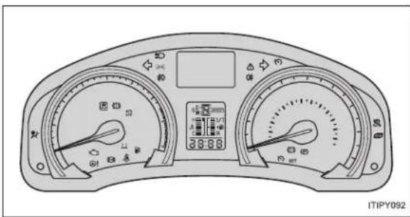
text_image
ITIPY092■Warning lights

Brake system warning
light (red)
P. 617P. 619

"LKA" indicator light*
[Non-Text]

Charging system warn-
ing light P. 617P. 620

Cruise control indicator
light
Dynamic radar cruise
control indicator light*

Malfunction indicator
lamp P. 618P. 620

control indicator light*
广力云智慧零售收银系统

SRS warning light
P. 618 P. 620

Speed limiter indicator
light*

ABS warning light
P. 618P. 619

Electric power steering
warning light

Brake system warning
light (yellow) P. 618P. 621

Low fuel level warning
light

"PCS" warning light*
P. 619P. 621

Seat belt reminder light
-

"AFS OFF" indicator
P. 619P. 622

Master warning light
[Non-Text]

Slip indicator light*
P. 619
*: The light flashes to indicate a malfunction.
The warning message is displayed
P. 624
If a warning message is displayed
What to do if...
What to do if...
What to do if...
GAS STATION INFORMATION

text_image
Auxiliary catch lever P. 531 Fuel filler door P. 129 Hood lock release lever P. 531 Fuel filler door opener P. 129 Tire inflation pressure P. 739 ITIPY079| Fuel tank capacity (reference) 60 L (15.9 gal., 13.2 Imp.gal.) | |
| Fuel type P. 131, 725 | |
| Cold tire inflation pressure P. 739 | |
| Engine oil capacity(Drain and refill — reference) | P. 727 |
| Engine oil type P. 727 | |